Designing Ground Control Points for a Traceable Drone Survey
Plan GCP locations, visible targets, coordinate measurement, reference systems, and field records so mapping control can be checked from the ground to processing.
Define the role of control before placing targets
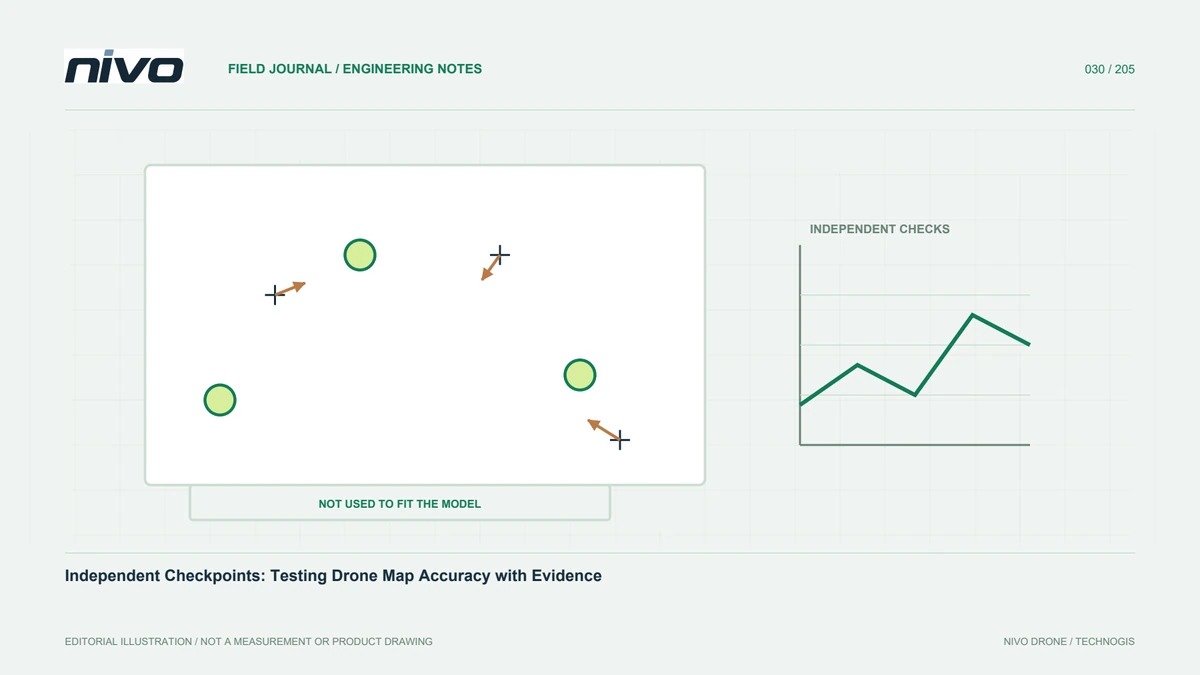
Ground control points connect the image-derived model to surveyed coordinates. Because they are processing inputs, their quality affects block orientation and shape. Define the reference system, survey method, required quality, and final products before placing targets. Separate GCPs from checkpoints reserved for independent testing. A point already used to constrain a model cannot simultaneously serve as independent evidence of that model's accuracy. Planning these roles early clarifies the survey budget and prevents every available reference point from being consumed as control while processors try to improve a difficult solution.
Distribute control around project geometry
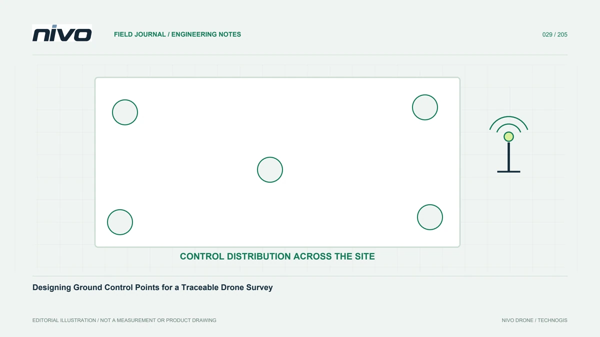
Consider the area's shape, elevation range, and image blocks. Placing all targets beside an accessible road may be convenient but leave other parts poorly supported. Along a corridor, distribute references through its length and changes of direction. On rolling terrain, include relevant elevations where safe measurement is practical. No single pattern or count automatically suits every project. Start from geometry and required quality, then assess a test block. Document inaccessible areas so processors and recipients understand where control support is limited rather than assuming it is uniform across the complete survey boundary.
Choose stable, identifiable locations
Targets need a surface that remains stable between surveying and photography. Avoid movable objects, active material piles, flexible vegetation, and places easily obscured by vehicles. The centre must be recognisable from the camera, not merely obvious to someone standing beside it. Consider shadows, background colour, flooding, and viewing direction. Coordinate with site staff so targets remain undisturbed. When using an existing marking, define the exact geometric point: a corner, a nail centre, and a line intersection are different references. Ambiguity can create inconsistent image marking even when field coordinates were measured carefully.
Match target design to image detail
Choose target size and pattern against planned GSD and the ability to locate its centre repeatedly. A target appearing as only a few pixels can be difficult to mark consistently; an unnecessarily large one can interfere with site activity. Use suitable contrast and keep securing material away from the centre. Inspect a test photograph at working height. On slopes, consider how the tilted surface appears from above. Record target dimensions, materials, and installation photographs. A conspicuous shape is useful only if it defines a clear and repeatable centre that remains recognisable throughout the source images.
Measure with a consistent survey procedure
Select a method suitable for accuracy needs and local conditions. For GNSS work, record solution information, relevant observation details, antenna height and its measurement convention, and correction source. Do not accept a coordinate solely because one instrument status appears satisfactory. Trees, buildings, reflective surroundings, and communication interruptions can affect observations. Repeated measurements or checks against established references can reveal errors hidden in a single observation. Ensure the team understands vertical versus slant antenna-height measurement for its equipment. An incorrect height record can influence the apparent elevation behaviour of an entire block.
Keep datum, height, units, and columns consistent
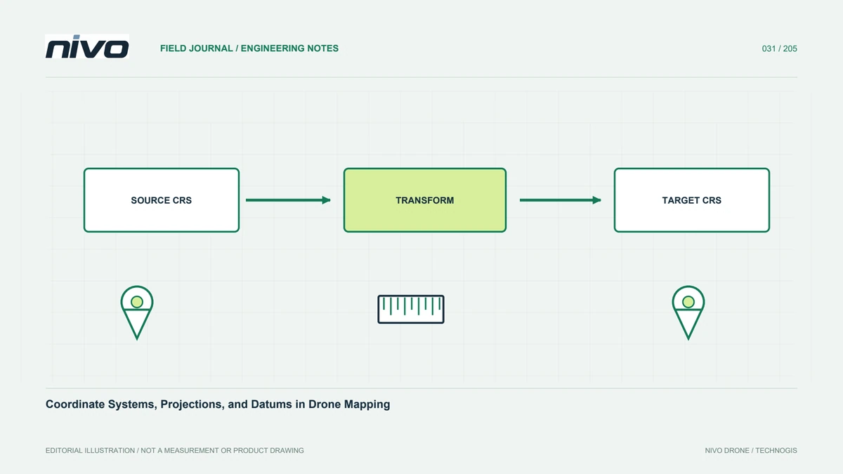
The coordinate list must identify its horizontal reference, units, height system, and any transformation. GNSS ellipsoidal heights cannot simply be treated as orthometric or project-local elevations. Preserve original coordinates when creating transformed versions and document the relationship. Check column order before import, particularly easting versus northing and longitude versus latitude. Display points on a map before full processing. A quick location check can reveal swapped columns, missing signs, or unit mistakes much earlier than repeated processing attempts. Coordinates without a clear reference definition are not a complete basis for combining a survey with other project datasets.
Make each target traceable
Use one unique identifier across field forms, coordinate lists, photographs, and processing projects. Record surveyor, time, instrument, method, relevant quality information, conditions, and any target changes. Take both close and wider contextual photographs. Preserve reasons for rejection or resurvey. Do not silently replace coordinates because different team members may otherwise process different versions. Good records let someone understand the control without having attended the fieldwork. They also support repeat surveys months later, when targets or staff may have changed and the original installation cannot be reconstructed from memory alone.
Evaluate control within the wider quality system
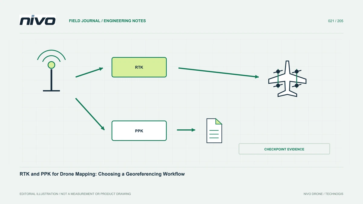
After initial processing, review GCP residuals alongside block geometry and independent checkpoint results. Small control residuals do not prove that every part of the model is correct. Investigate misidentified centres, questionable measurements, or weak distribution methodically. Do not remove points merely to improve summary statistics. Report which points were used or excluded and why. Aircraft RTK or PPK can form part of a georeferencing strategy, but control design and testing still follow project needs. A discussion of NiVO configuration is most useful when grounded in an evidence-based plan for data acceptance.
Build a complete record for one point
A target record can include its identifier, original and transformed coordinates, centre photograph, contextual photograph, and measurement summary. Use the same structure throughout the project. If a target moves because machinery access changes, close its old identity and document the replacement rather than assuming continuity. Processors can then distinguish images showing the earlier and later target. This discipline reduces the risk of assigning a correct coordinate to the wrong object. Control quality is a chain of evidence from field measurement to image marking, not just an apparently precise number in a spreadsheet.
Illustrative scenario: a control target moves during site work
Consider a hypothetical construction survey where a target is installed beside a temporary access lane. The ground team measures its centre and photographs the surroundings. Before the drone flight, site staff move the target to allow a delivery vehicle through. A later photograph still shows the familiar target pattern, but it no longer represents the surveyed point. During processing, the operator notices that the field overview image and aerial context do not agree. Rather than forcing the model to match the original coordinate, the team traces the target identifier, observation time, and movement reported in the site log.
The moved target is not silently reused. Its original record is retained, the affected observations are identified, and any replacement receives a clearly documented relationship or a new identity. The team assesses whether remaining control still supports the planned processing and whether a repeat measurement is required. Checkpoints reserved for assessment are not automatically promoted to control merely to make processing proceed. The report explains the exclusion and its consequences. This hypothetical case illustrates why control quality includes stable physical identity and evidence linking ground measurement to image marking, rather than only a coordinate list that appears precise when opened in a spreadsheet.
The contrasting choice is between preserving fewer valid references and retaining an invalid point simply because it makes the control layout appear balanced. The team chooses validity, then evaluates the consequences rather than claiming the old design still applies. Handover includes the target status table, contextual photographs, and the final list actually used. A reviewer can follow the identity change without consulting personal messages. This also prevents the displaced target from being reused accidentally when someone processes the same photographs again at a later date.