Drone Inspection of Solar Panels: Planning RGB and Thermal Evidence
Plan solar-panel inspections around module identities, operating conditions, reflective surfaces, paired RGB and thermal evidence, coverage checks, and technical follow-up.
Start with module identities and inspection objectives
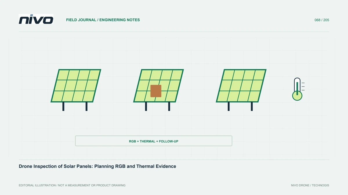
Connect every observation to a module or system part that maintenance staff can relocate. Obtain layouts, row identities, numbering, and relevant operating information. Define whether the work concerns visual inventory, thermal-pattern screening, or documentation after a particular event. Each purpose needs different evidence and follow-up. Do not promise complete diagnosis from one aerial view. State coverage, evidence type, and limiting conditions. This is especially important where many modules look alike and an isolated image otherwise provides little practical indication of where a technician should investigate.
Choose a relevant observation opportunity
Module patterns depend on operating state and environment. Coordinate with the facility so relevant system circumstances are known and recorded. Consider sunlight, clouds, wind, and surface conditions according to the selected method. An unsuitable operating state may prevent images from establishing either the presence or absence of a problem. Do not transfer requirements between procedures or system types without checking applicability. Record changes during the work so technicians can interpret patterns and decide whether another observation under different circumstances is necessary.
Manage reflections and viewing angle
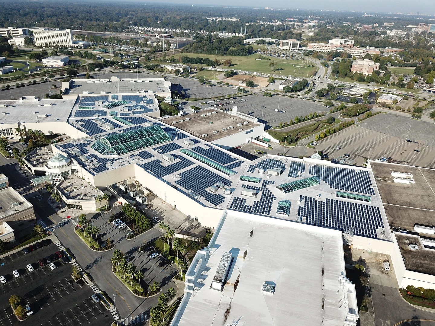
Panels can reflect surrounding radiation, making viewing geometry important in thermal and RGB interpretation. A difference seen from one direction should be considered alongside possible reflection. Plan views that maintain target readability and module identification within assessed operating limits. An additional angle can help test alternatives where appropriate. A bright thermal region is not automatically higher internal temperature. Record viewing direction and material context. This reduces overinterpretation and provides useful information when the asset team later verifies a reported anomaly.
Specify the detail that must be visible
Module and component sizes determine required image detail. Trial the planned geometry to establish readable evidence. RGB should support identity and visible condition; thermal output should meet the agreed pattern or measurement purpose. Digital zoom does not justify claiming detail absent from the original. Review stored files, not only live transmission. If neighboring modules cannot be distinguished reliably, revise naming and acquisition design. Early trials with recipients create a shared standard before the team gathers a large facility-wide dataset that may be difficult to repeat.
Connect visible and thermal evidence traceably
Each anomaly should have evidence identifying the module and showing the pattern. RGB may explain dirt, shadow, or surface circumstances, while thermal provides complementary observations. Connect pairs using time, asset identity, or consistent records. Different sensor fields of view mean correspondence must be checked, not assumed. Retain originals for renewed assessment. Where temperatures are reported, confirm that the data format and required parameters are available. Good evidence management prevents an interesting image from becoming a finding that cannot be confidently assigned to a particular module.
Control completeness through a coverage register
Repeated rows make it easy to collect duplicate images while missing parts of the site. Track modules or asset groups that have adequate observations and those needing more work. Review obstructions, edges, and areas under different illumination. Flying over an area does not prove the camera viewed it suitably. After each block, check sample files and their identity links before proceeding. Completion should follow the agreed inspection requirement rather than merely reaching the end of a stored route or accumulating a large image count.
Verify causes with facility technicians
Different thermal patterns can have several explanations. Relate them to operating data and appropriate technical investigation. Record observations neutrally before assigning a cause, comparing relevant similar modules where possible. Electrical testing and equipment interventions belong to authorized staff following facility procedures. Drone operators should not extend imagery beyond its evidential or professional scope. Give each finding a clear follow-up requirement, including further observation when necessary. This allows aerial screening to support maintenance priorities without pretending to replace assessment of the complete generating system.
Organize the report through asset identity
Include module number, layout location, date, conditions, thermal evidence, RGB context, and reason for review. Distinguish observed anomalies and verification needs from confirmed defects. Where priorities are used, explain their technical basis and who agreed them. Do not deliver an unindexed folder that leaves the owner to reconstruct relationships. Allow status updates after investigation. Actionable outputs connect inspection effort to actual maintenance work and create an archive suitable for repeated observations and review of what happened after earlier findings were reported.
Evaluate value through follow-up outcomes
After delivery, check whether staff can identify targets and review findings without confusion. Record verification results, actions, and cases influenced by capture conditions. Use them to improve routes, views, and record keeping. Bring module examples and desired outputs to NiVO payload consultation so the selected RGB or thermal arrangement can be tested meaningfully. Success is not the number of colored anomalies. It is trustworthy evidence helping the team choose further inspection or action, with observation limits still clear and available for later review.
Illustrative case: connecting a solar-panel anomaly to the correct module
Imagine a hypothetical solar facility where the aerial map and the maintenance register use different row labels. The inspection team records several thermal patterns with paired RGB images, but the first draft report identifies them only by coordinates and a screenshot. The maintenance coordinator cannot confidently determine which module should be reviewed because adjacent rows contain visually similar units and the available coordinate evidence has not been assessed for that purpose. The team therefore treats asset association as an unresolved part of the finding, not as a clerical detail to fill by guessing.
Before final delivery, the owner and inspection lead agree a cross-reference between the layout and the maintenance register. Existing source images are checked for defensible locating context, and any association that cannot be established remains marked for follow-up. Operating circumstances, lighting changes, viewing direction, and relevant source-file identities accompany each thermal observation. The examiner reviews whether a pattern could be affected by shadow, reflection, or another visible condition before deciding what technical investigation is appropriate. The record does not convert a colorful thermal patch into a confirmed electrical defect or prescribe an intervention from imagery alone.
The decision compares delivering a preliminary alert with explicit limits against collecting additional evidence needed for a fully relocatable finding. Either can be useful if its status is understood. Handover requires a stable module reference, paired context and detail, stated observation conditions, and a named verification question. A technician absent from the flight tests whether the package is understandable. The case is accepted only when the report can support the agreed next task, demonstrating that inspection value depends on the link between observation and maintenance action rather than the number of anomalies marked on a map.