Mapping Road Corridors with Drones: Keeping Data Connected along the Route
Plan corridor segments, image geometry, control, block joins, and GIS delivery so a long road survey remains connected, consistent, and understandable to users.
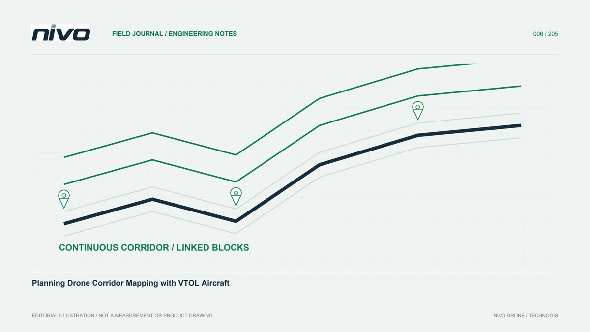
Design for a long, narrow geometry
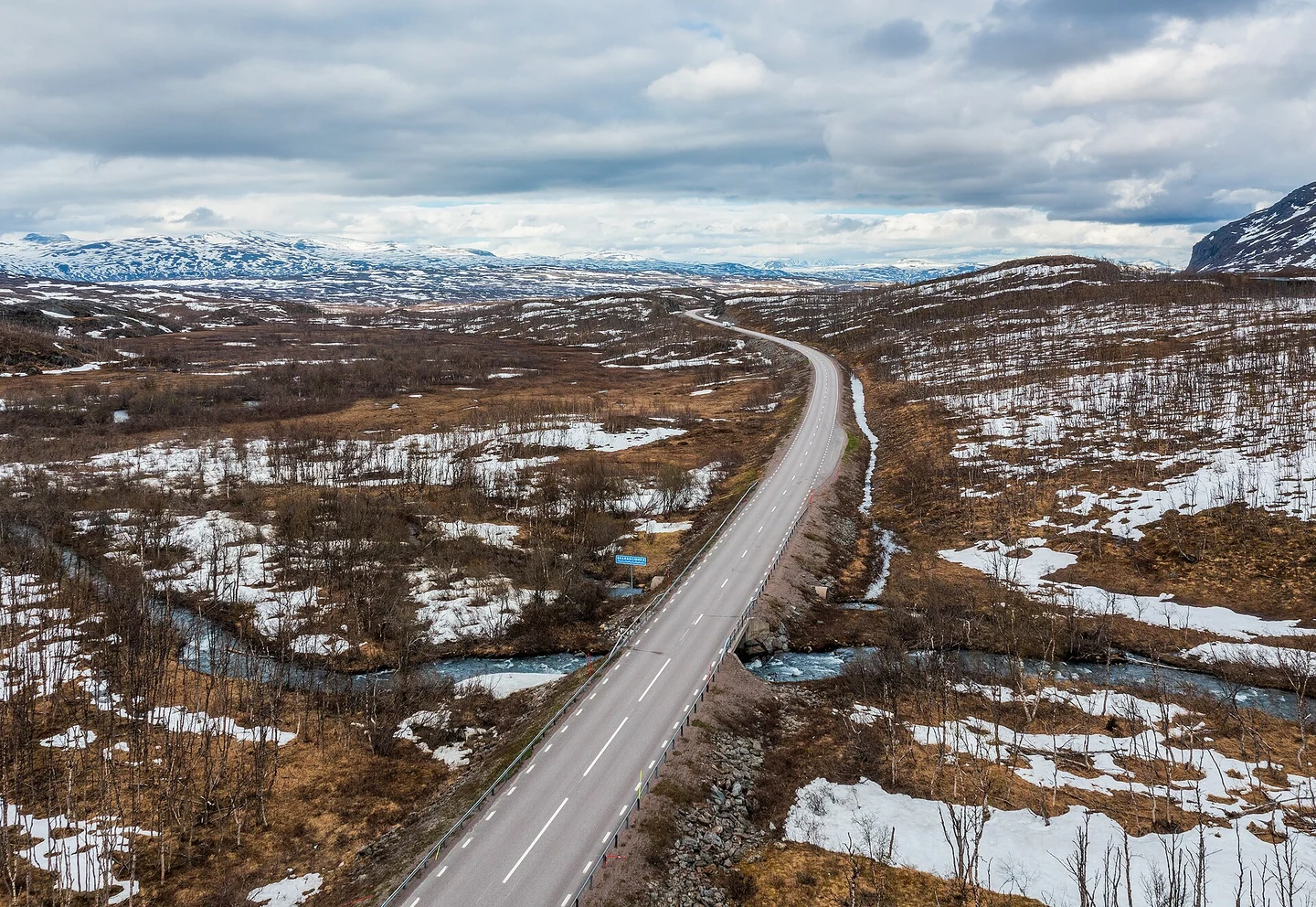
A corridor differs from a roughly square mapping block. A narrow chain of images can have weak geometry without suitable support. Roads also bend, change elevation, pass vegetation, and approach active facilities. Define corridor boundaries, required information width, and products. Distinguish observed area from delivery limits, and identify junctions, bridges, slopes, and assets needing special attention. This directs lines, control, and checks to actual requirements. Simply clipping a broad-area template into a narrow strip can overlook the geometric consequences, leaving a survey that appears covered on a plan but lacks the relationships needed for dependable reconstruction.
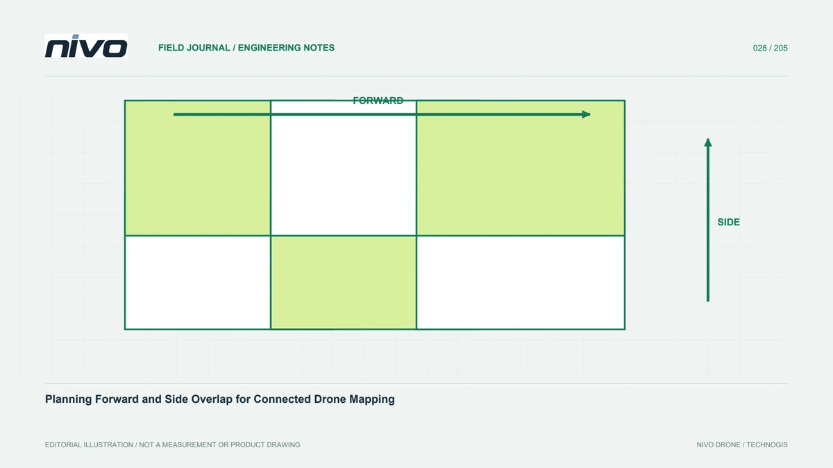
Plan connections when dividing the route
Long corridors often require several flights or working days. Place segment boundaries where useful connectivity and checks are possible, not solely where a battery estimate ends. Provide shared observations appropriate to conditions so the model does not depend on a few weak images at an endpoint. Record segment, date, configuration, and operational changes. At session joins, inspect objects that may move or change. Map the intended relationships for processors. Clear segmentation supports local corrections and staged handover while maintaining consistent positioning and meaning across the complete route users need to assess.
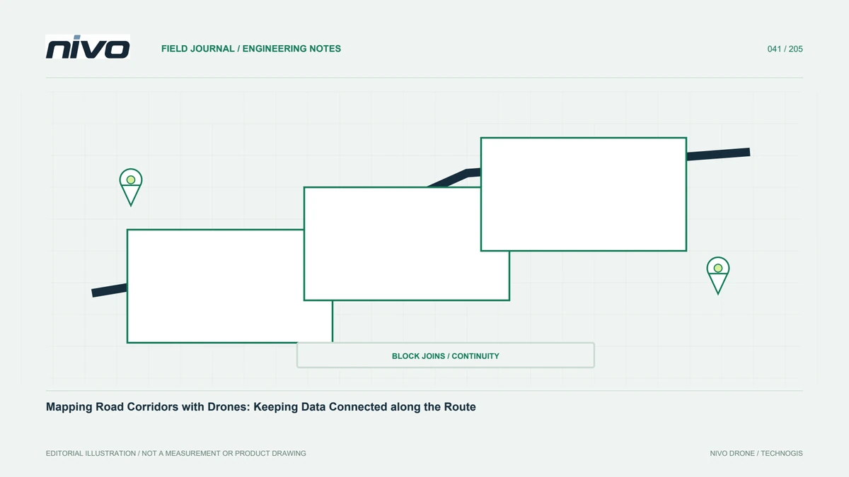
Review bends and endpoints carefully
Sharp bends and corridor ends can have different coverage from straight sections. Inspect image footprints on both sides of bends and confirm that required objects were actually observed. Terrain and buildings can reduce effective overlap. Where an additional pattern is justified, define its purpose and use approved procedures within equipment capability. Avoid spontaneous manoeuvres merely to chase a gap. Test a segment representing difficult geometry before applying a pattern everywhere. Distinguish support for image relationships from extra detail required for a particular object, so every additional capture has a clear objective and an assessable result.
Distribute references through the corridor
Control and checkpoints should represent route length, elevation changes, and relevant block divisions. Points near one access location cannot reveal quality at distant ends. Separate processing control from independent tests and select survey methods for actual conditions. Record limitations around buildings, vegetation, and restricted access. If chainage or section identifiers are used, link point names to them without replacing complete coordinates. Verify compatibility with project references before full processing. Aircraft GNSS can support georeferencing, but acceptance still needs distributed checks that explain how different parts of the corridor were assessed.
Record activity and changing objects
Traffic, construction, equipment, and shadows can change during capture. The mosaic may contain cut or doubled moving objects. Coordinate scheduling and access with site management and follow applicable permissions and operating procedures. Record observation times and events affecting interpretation. For repeat road surveys, also document intervening work. Aerial data records a time-dependent condition, not a continuously updated state. Time and activity context help users distinguish physical infrastructure change from differences caused by exposure timing or mosaicing, avoiding conclusions about an asset that the source images do not support.
Separate visual mapping from terrain information
RGB mapping helps interpret markings, facilities, and visible conditions. Questions about profiles or landform require a suitable ground representation. Ground beneath bridges or canopy should not be assumed observed because the orthomosaic looks complete. Identify supplementary measurements at critical locations. When creating longitudinal or cross-profiles, describe elevation source, sampling, and whether values represent ground or overlying objects. Give different products clear names and metadata. This prevents users extracting heights from a raster that was never designed or tested to answer the engineering question currently being considered.
Inspect joins in several representations
Review orthomosaics, clouds, and relevant elevation products across segment joins. Matching colour does not prove matching geometry, and a colour difference does not necessarily indicate positional error. Use stable features, profiles, and checkpoints to separate those characteristics. Look for abrupt elevation changes, doubled patterns, and gaps near session boundaries. Map findings to source segments. Recheck combined outputs rather than relying only on per-segment acceptance, since merging can introduce grid, extent, or reference issues visible only when the corridor is treated as one connected dataset.
Package data around the user's workflow
Recipients may work by road section, chainage, district, or a particular tile scheme. Agree the organisation early and provide an index. Retain coordinates, units, height references, and valid coverage in every package. Deliver the main imagery or models with quality records and limitations. Distinguish lightweight previews from approved analytical data. Link outputs to their dates and source segments. A handover aligned with the user's process reduces searching and the risk of using an obsolete version, especially where the corridor is captured and revised through several stages rather than delivered in one session.
A three-condition corridor example
A route crossing open ground, a vegetated valley, and an urban junction needs checks for each condition. Test ground support in the valley, image relationships at the junction, and stable connections between segments. Distribute control and checkpoints across the route. Review a combined profile after sample processing before fixing the final approach. Discuss NiVO and payload options against observed requirements and integration needs. Judge success through connected geometry, required information completeness, and the ability to trace each output to capture and assessment evidence, rather than by total mapped length alone.
Illustrative scenario: an inaccessible join on a road corridor
Consider a hypothetical road corridor divided into three capture segments. The most convenient battery-change location would place a block join beside a vegetated bend with restricted ground access. The planner compares that convenience with the need for reliable connections and distributed assessment. The team reviews image footprints around the bend and existing reference opportunities along the corridor. It does not assume that control near the launch area establishes the quality of distant segments. Before finalising the plan, the proposed join is evaluated against stable identifiable surfaces and the coverage permitted by the operating and site-access arrangements.
The chosen segmentation records common observations and assigns clear identities to each session. Where reference measurement remains impractical, the limitation is stated instead of inventing a representative checkpoint result. Processors receive the join plan, capture dates, relevant camera changes, and notes about ongoing road activity. After reconstruction, reviewers examine the corridor connection in imagery and elevation profiles, not only in a colour overview. A visually smooth seam is insufficient if profiles or independent evidence suggest a geometric discontinuity. Any additional capture must have a defined purpose and follow the approved operating plan.
Handover includes a segment index, valid coverage, reference descriptions, and the status of each join. Users working by road section can locate the exact data and understand where it was tested. If a connection cannot meet the agreed purpose, that section remains limited or requires further work rather than being hidden in a merged file. This hypothetical example shows how a corridor plan balances field convenience against evidence needed for a connected product, while keeping the consequences of inaccessible locations visible to the people who will use the data.