Planning Forward and Side Overlap for Connected Drone Mapping
Understand image overlap, terrain, texture, and actual camera coverage so a mapping block remains connected and missing observations are found before demobilisation.
Treat overlap as a relationship between images
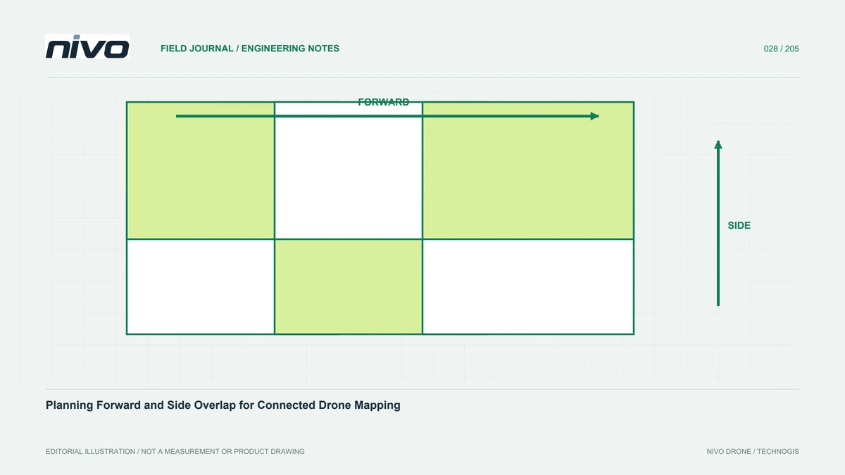
Overlap is the area observed again in another image. Forward overlap connects successive photographs along a route; side overlap connects neighbouring flight lines. These relationships allow matching of the same features from different viewpoints. More photographs alone do not guarantee strong geometry if their viewpoints are almost identical or their surfaces have little texture. Plan overlap around object shape, relief, camera angle, and the intended product. Set trigger spacing and line separation from those needs, rather than treating one percentage as a universal setting for every environment and reconstruction task.
Connect triggering with aircraft movement
Image spacing depends on footprint length and selected forward overlap. With time-based triggering, a change in ground speed changes the spacing between photographs. Wind can therefore make opposite directions behave differently from the simulation. Distance-based triggering can connect exposure events more directly with movement, but the camera must still capture and store images reliably. Check for delays, dropped frames, and recording limits. Compare trigger logs and image timestamps after a test. The number of files on a card is useful, but it does not by itself show that observations were captured at the right intervals.
Adjust expectations for surface texture
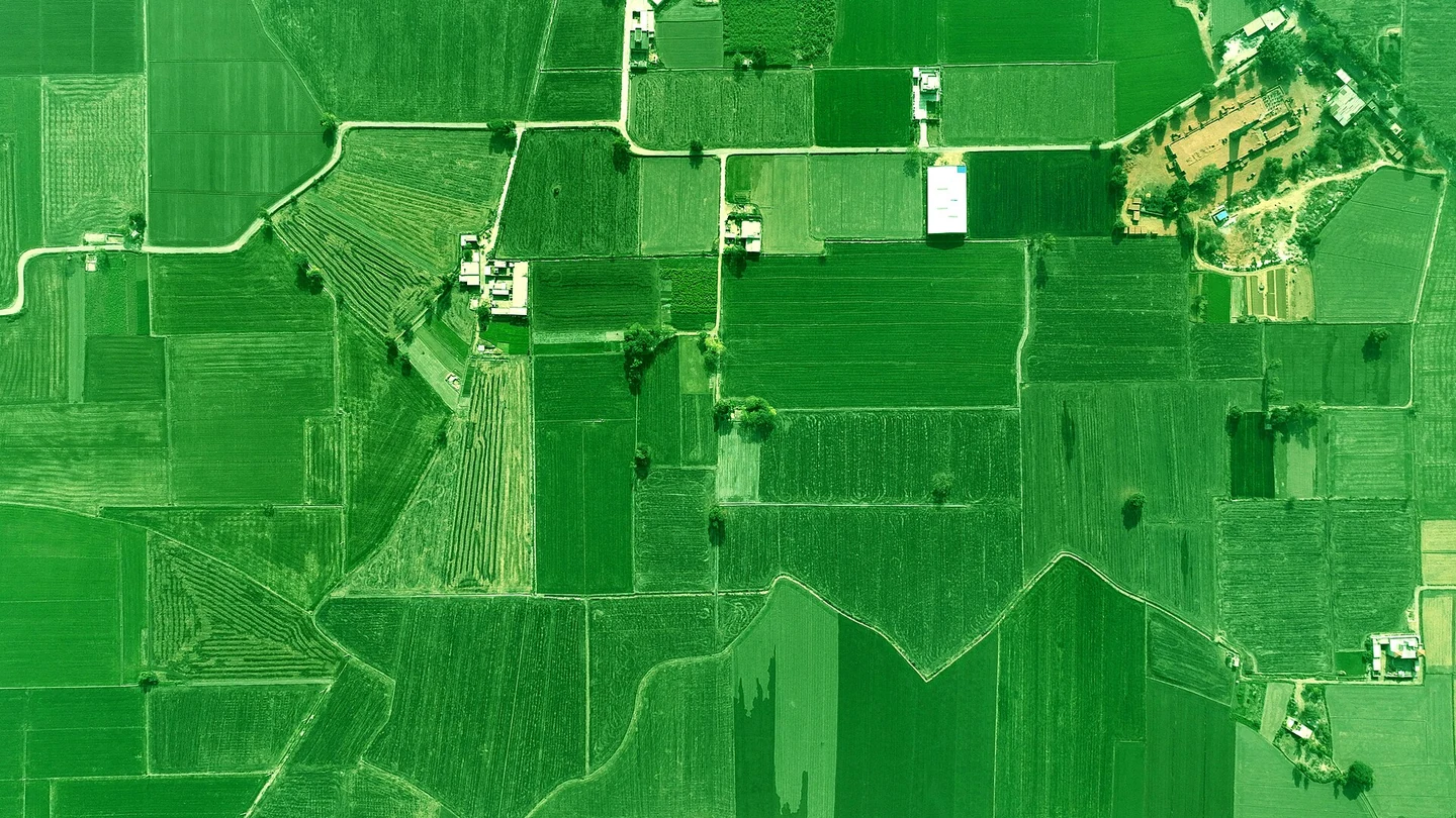
Clearly textured ground differs from repetitive crop rows, uniform roofs, or sand. Repeating patterns can make locations difficult to distinguish, while water, moving vegetation, and changing shadows complicate matching. OpenDroneMap's flying guidance discusses overlap in relation to scene complexity rather than presenting one percentage as appropriate everywhere. Use software recommendations as a starting point for testing. Difficult areas may justify additional viewing directions and early sample processing. High overlap cannot replace sharp images, adequate illumination, and a sound reference framework, so assess these factors together before increasing coverage indiscriminately.
Check how relief changes effective coverage
A camera footprint becomes smaller when the surface is closer. Line spacing planned for low ground may therefore provide less side overlap over a hill or tall roof. Slopes can also hide surfaces from one direction. Review terrain profiles and raised objects before finalising the route. If terrain-following is used, check the suitability of its elevation source and the operating plan. Complex terrain may be better divided into controlled blocks. Their boundaries still need deliberate common observations so processing is not forced to rely on a few weak photographs at a difficult connection.
Choose geometry for the intended product
Orthomosaics, surface models, and detailed building models do not necessarily need identical capture patterns. Near-vertical imagery can support overhead mapping, while façades and stepped structures need viewpoints that reveal their sides. Cross-lines or oblique photographs can strengthen particular relationships but add field and processing work. Evaluate these choices within permissions, obstacles, and aircraft capabilities. Test representative areas before adopting a pattern across the whole project. Every additional line should have a purpose, such as connecting blocks, revealing a surface, or checking a previously hidden area, rather than merely increasing image count.
Plan support beyond the final map boundary
The area to be delivered generally needs suitable observations around its edges so boundary objects are supported by enough images. Stopping capture exactly at the product polygon can leave weak geometry at its perimeter. Distinguish the flight area, image coverage, and delivery boundary in project documents. Additional support must remain within the permissions and operating limits applicable to the site. For example, a plantation block may benefit from outside support lines, but neighbouring land cannot simply be assumed available. Resolve these boundaries during planning so data requirements do not conflict with access or authorisation once the team is mobilised.
Inspect actual coverage before leaving
After capture, compare image counts, camera positions, and interruption notes with the plan. Look for gaps, broken lines, and unexpected height changes. Open photographs in suspicious areas because a position marker does not prove that its image is sharp or correctly recorded. If practical, run preliminary matching on important blocks. Early checks help decide whether supplementary capture is needed before targets are removed or the team leaves. Prioritise block joins, corridor ends, high terrain, and low-texture locations. These are often more vulnerable than the easy central area normally chosen for a quick visual preview.
Record why parameters were selected
Acquisition records should identify planned overlap, route pattern, trigger method, height range relative to terrain, and field changes. Explain differences between blocks so processors understand where special treatment may be necessary. For recurring surveys, compare planned relationships with processing results and use those findings to improve the next plan. Image connectivity results from camera, aircraft, terrain, and planning working together. When discussing a NiVO configuration, use representative test evidence to connect efficiency with the quality needed for the map, rather than choosing overlap only to maximise a quoted area-per-flight figure.
Check the join between two flights
When a site is split across flights, verify their common observations rather than checking only that each polygon was covered independently. A join through uniform forest may need support near more identifiable terrain or structures. Tell processors about battery changes, lighting changes, and camera-setting differences. Review the resulting join in both the orthomosaic and elevation representation: consistent colour does not prove consistent geometry. This example links overlap decisions to the final product users receive and helps ensure a visually tidy mosaic is also supported by a defensible connection between its source blocks.
Illustrative scenario: reconnecting two image blocks
Imagine a hypothetical corridor survey split between morning and afternoon flights. A battery change places the join over a uniform grass area, and the afternoon route begins after the light has changed. The coverage map appears complete, yet preliminary processing forms two weakly connected groups. The processor does not immediately increase every reconstruction setting. Instead, the team inspects the actual photographs near the join, checks trigger timestamps, and distinguishes missing imagery from photographs that exist but contain little stable texture. Field notes show that both flights recorded a nearby fixed service structure from different directions.
The team evaluates whether those observations provide a defensible connection and whether additional approved capture is still needed. Any supplementary line has an explicit purpose: strengthen the relationship around the join while observing the required boundary area. After processing, reviewers examine both colour continuity and geometric profiles across the connection. Independent checks remain separate from the features used to establish alignment. The acquisition record preserves the flight split, lighting difference, and reason for the revised plan. This scenario shows why a fully coloured coverage polygon is only an initial check; useful overlap must produce relationships that survive inspection in the resulting model and map.
For acceptance, the team contrasts two remedies: collecting useful connecting observations or changing processing settings while the source remains weak. The selected remedy must improve evidence at the join without damaging already satisfactory areas. A retained profile set and a map of aligned cameras form part of the review package. If the connection still fails, the boundary is not hidden beneath cosmetic colour blending. Its status remains unresolved or explicitly limited until a defensible observation relationship can be established and checked.