GNSS Antenna Cables and Active-Antenna Power Checks
Review antenna and receiver compatibility through RF cable identity, connector condition, gain definitions, power requirements, and manufacturer-supported diagnostics.
Identify the whole RF chain
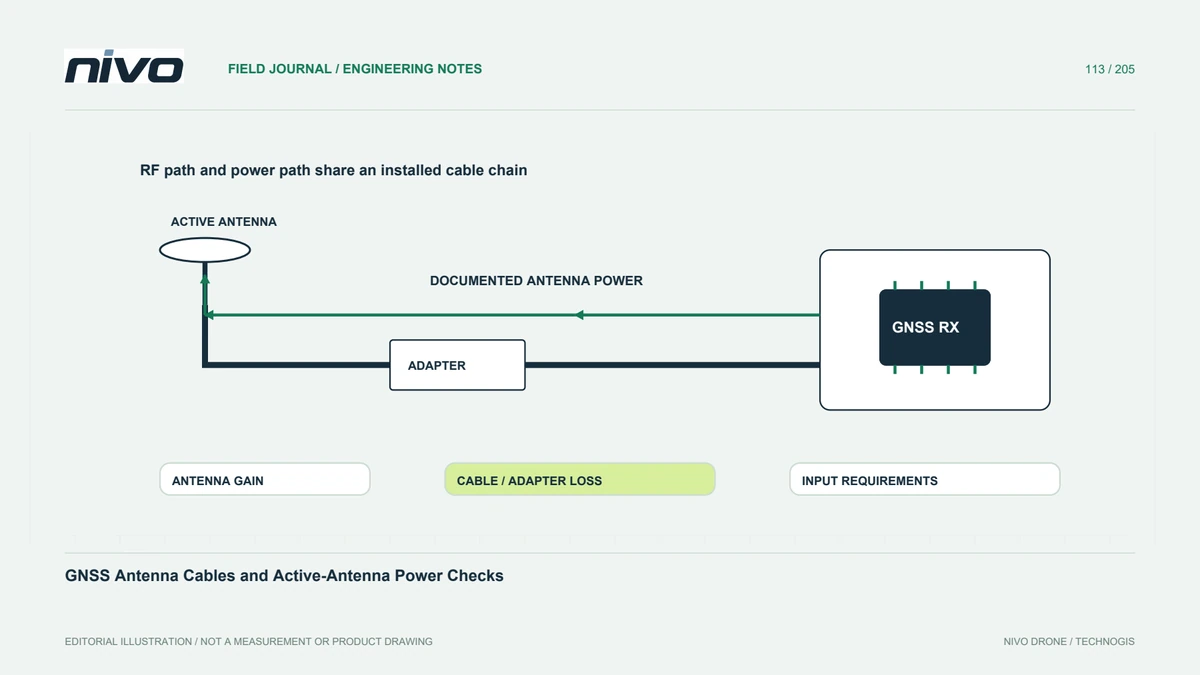
The antenna, coaxial cable, adapters, connector, receiver input, and any antenna-power arrangement form one integration chain. Record their actual models and installation. A connector fitting mechanically does not prove suitable RF or electrical behavior. Distinguish active and passive antenna requirements using the receiver and antenna documentation. This prevents a replacement cable or antenna from being accepted solely because the receiver still displays some satellites after connection.
Keep gain and loss definitions separate
Antenna performance, amplifier gain, cable loss, and receiver requirements describe different quantities. A large combined gain figure is not a complete quality assessment. Read the manufacturer's definitions and permitted arrangement for the actual equipment. Do not infer that more amplification always improves reception. The integration record should show how the chosen components relate, without inventing a universal cable length, amplifier setting, or compatibility rule for every GNSS installation.
Review active-antenna supply information
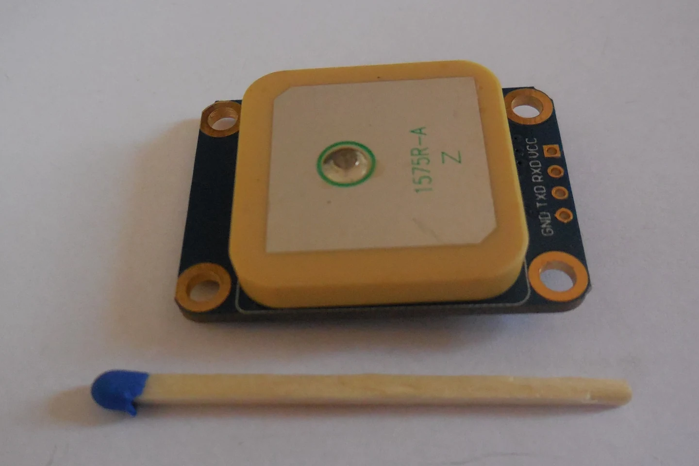
Active antennas require an appropriate supply arrangement, which may be provided through the receiver's RF connection depending on the design. Confirm documented requirements and supported monitoring information. An available open-circuit or short-circuit indication has meaning within that implementation; it is not a complete test of signal quality. Competent personnel determine authorized electrical checks. Do not apply external power or bypass protection based on a generic troubleshooting suggestion.
Inspect handling and cable geometry
Look for documented evidence of pin damage, contamination, crushed sections, unsupported connectors, and bends inconsistent with the cable guidance. Compare routing after transport and payload work. Follow approved procedures for disconnecting and reconnecting RF components. A visible scuff does not establish internal failure, while a clean jacket does not prove the path is intact. Preserve removed parts where examination may help distinguish a connection issue from an antenna or receiver fault.
Compare receiver evidence under known conditions
Review relevant signal and antenna-status information using consistent device settings and a documented environment. Changes in satellite geometry or surrounding reflections can complicate comparisons. A better-looking indicator after replacement needs interpretation alongside the actual change. Record what the check establishes and what remains uncertain. If positional quality matters, assess it through suitable independent evidence rather than treating signal strength as a direct guarantee of accurate coordinates.
Maintain an identifiable approved assembly
Keep antenna, cable, adapter, receiver, supply references, routing photographs, and accepted checks together. Mark replacements and explain when a new combination needs review. This gives NiVO service teams a complete installation description instead of an ambiguous request for any matching GNSS cable. It also preserves the distinction between restoring connectivity and demonstrating that the assembled RF chain supports the intended observation and positioning workflow.