Here GNSS from CubePilot: Installation Context for Survey Drones
Understand CubePilot Here GNSS models, antenna placement, camera reference relationships, corrections, configuration records, and verification of survey data.
Identify the GNSS product clearly
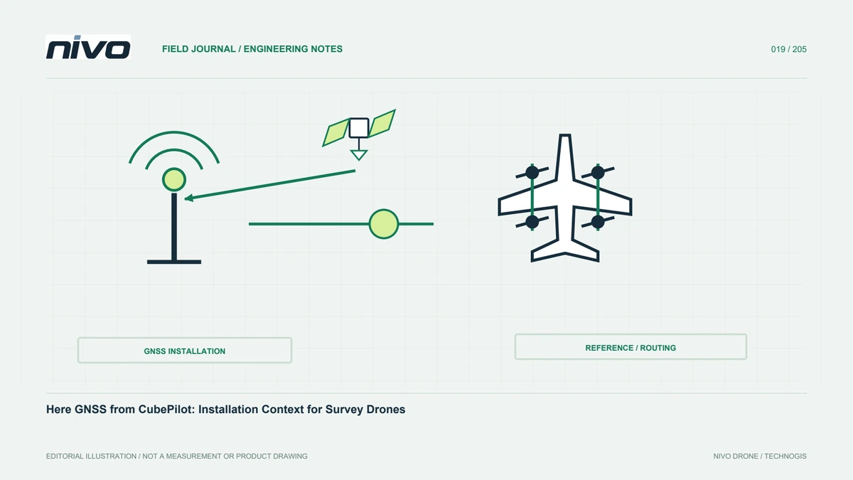
In this drone context, Here means CubePilot's GNSS product family, not a similarly named mapping service. Specify the full model in procurement and configuration documents. Family members may differ in functions, connections, and firmware. The NiVO technology section associates Here GNSS with CubePilot, but this does not establish identical hardware on every aircraft. Installed equipment must be defined in the delivered unit documentation. Clear names ensure that support staff, operators, and processors discuss the same device rather than making assumptions from a broad brand reference.
Locate its role in the architecture
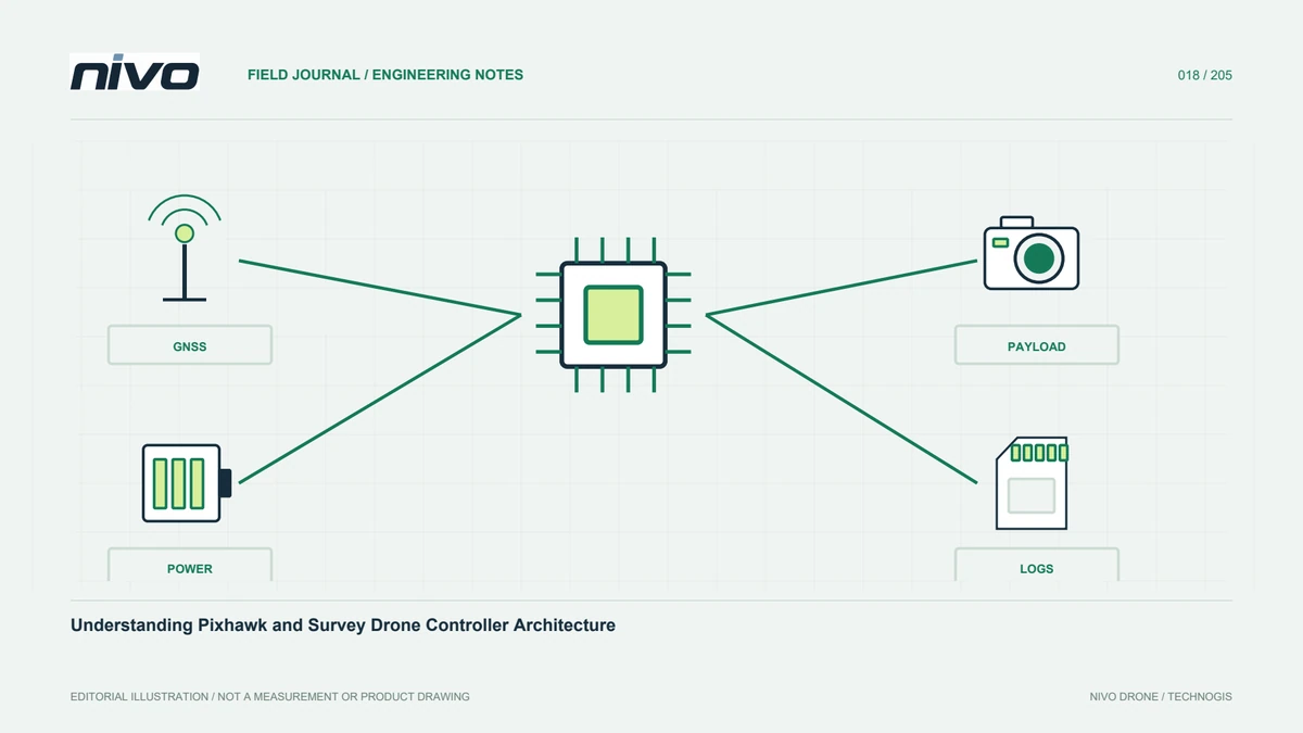
A GNSS module relates to navigation, but complete capabilities depend on model and integration. The Here 4 manual describes navigation and supporting interfaces; these should not become claims for every Here device or aircraft. Diagram the installed connections and functions actually used. Distinguish an available but unused interface from an accepted feature. This helps assess project requirements and route technical issues. Reporting the relevant function is more useful than describing an entire aircraft subsystem simply as GPS without identifying the device or data involved.
Follow the antenna integration design
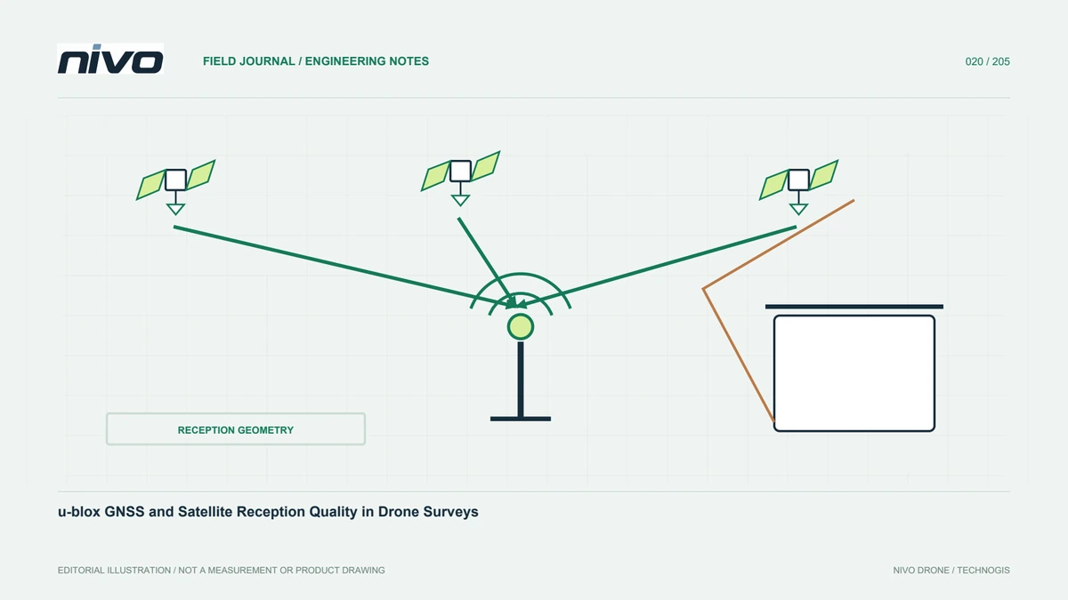
Structure, electronics, and other equipment can influence reception. Placement must follow manufacturer guidance and the integrator's assessment. Do not move a module merely to make the layout tidier. Record orientation, mounting, and relevant geometry. Transport reassembly should preserve the accepted arrangement. There is no universal installation distance in this article because structures, antennas, and electrical environments differ. The practical requirement is a recognisable and documented setup, with changes assessed before earlier acceptance evidence is reused for a newly arranged aircraft.
Understand the camera reference relationship
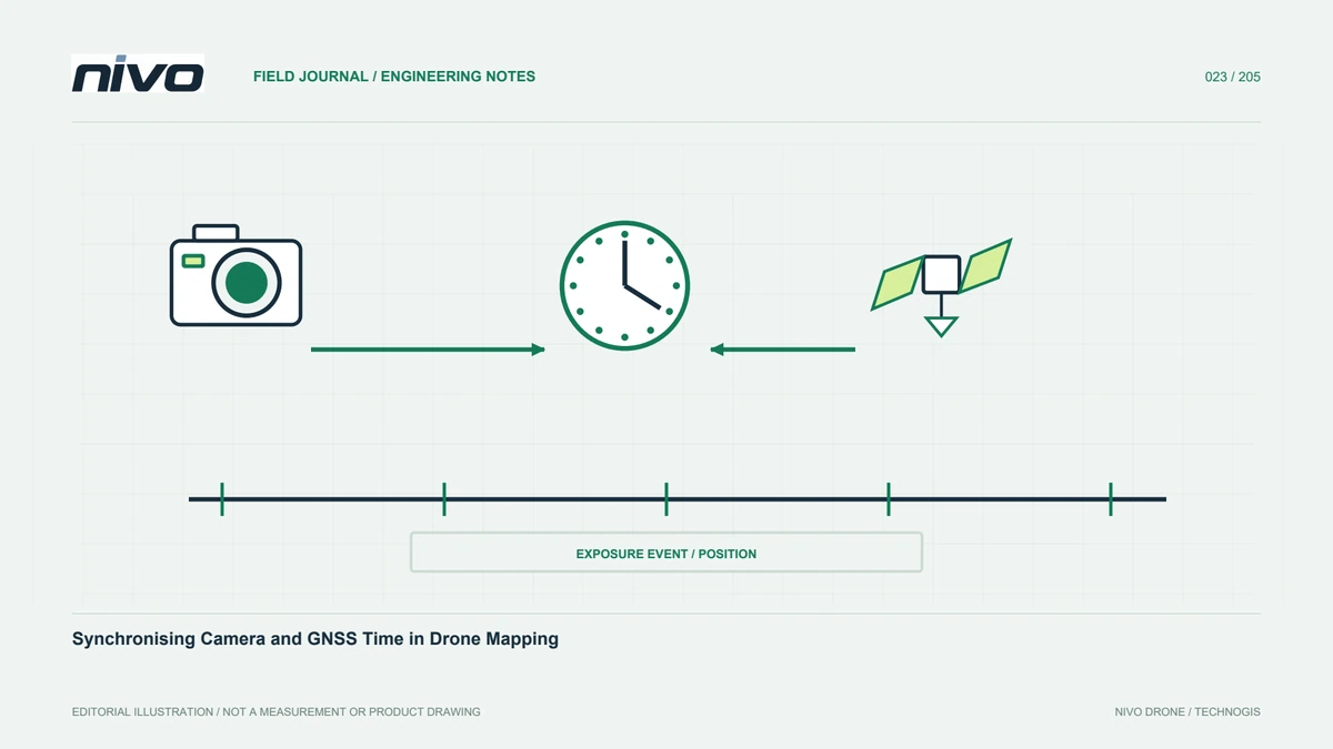
Where camera positions are used, the antenna reference does not automatically coincide with the imaging centre. Integrator and processor must understand the geometric correction and its source. A changed mount or device may require review. Record reference points, axes, units, and measurement definitions rather than numbers alone. This reduces sign and interpretation errors when another application or analyst uses the configuration. It also helps distinguish a GNSS positioning issue from an incorrect application of the relationship between antenna and sensor during processing.
Review the correction workflow
RTK capability needs a correction source, delivery path, and appropriate settings. A displayed solution status is useful but is not complete survey-quality evidence. Record source, time, and relevant conditions. If the configuration also supports later processing, confirm required files are actually recorded. A function in general documentation is not proof it is active. Plan this with the processor before acquisition, because some required observations cannot be recreated after the aircraft returns. A delivery checklist connects receiver capabilities with the actual project method.
Interpret indicators consistently
Lights and status messages must be read using the actual model manual and configuration. Experience with another device is insufficient. Training should connect device indicators with ground-station information and the appropriate checks. Observers need shared reporting terms. Record time and state when an indication differs from expectations. A precise description is more useful than saying the module looked normal. Consistent reporting allows technical personnel to connect an observation with logs and configuration evidence rather than guessing which indication the operator meant.
Control firmware changes
GNSS firmware and aircraft software belong in the configuration record. Updates require compatibility review and integrator procedures, not an assumption that the newest version suits every system. Keep the former identity and reason for change. Perform required checks after an approved update and record acceptance. This supports comparisons across periods and units. Without such records, a difference may be attributed to the survey environment when the receiver or its integration changed. Configuration control preserves the context needed for a defensible investigation.
Verify results independently
Assess final mapping with suitable control and independent checkpoints. Review coordinates and height definitions across sources. GNSS status cannot replace this evaluation. If results differ, investigate correction reference, timing, geometry, and processing before blaming the module. Complete evidence helps distinguish measurement, integration, and coordinate-presentation issues. State the limits of the available checks, especially when only part of a project is represented. The purpose is to prove the required product quality rather than infer it from the reputation of one component.
Provide usable documentation
Supply installed-model identity, relevant manuals, connection diagrams, configuration versions, and sample data. Users do not need every development document, but need enough for checks and meaningful support requests. Identify functions not yet integrated and update records after accepted changes. Here GNSS then has a clear role in the survey system. Users can connect device selection with acquisition, georeferencing, and quality assessment instead of relying on a brand name. The same package helps future operators understand the accepted arrangement when the original team is unavailable.
Illustrative case: restoring a Here GNSS installation after transport
Imagine a hypothetical team reassembling an accepted survey configuration after transport. The Here GNSS device and its mount can be recognised, but the operator notices that the available reference photograph does not show the relationship to the nearby payload installation. Instead of choosing a convenient position from memory, the team checks the actual model manual and the integrator's configuration record. The technical lead verifies mounting orientation, relevant connections, and the documented antenna-to-sensor relationship. The processor confirms which reference definitions are used in the georeferencing workflow. A device indicator is interpreted using the correct model documentation rather than experience with another product in the same family. If the installed arrangement cannot be matched with the accepted state, that uncertainty is resolved through the applicable assessment process. This hypothetical example promises no positioning accuracy and is not a flight instruction. Its evidence includes device identity, configuration version, defined geometry, and the required verification records. The final handoff gives the operator a reference that can actually be used during reassembly. It also prevents an attractive installation photograph or a familiar brand name from replacing the measurements and configuration information needed to explain the resulting survey data.
If the accepted geometry can be established, the team can restore the documented arrangement and complete the specified checks. If the layout has genuinely changed, it requires a new assessment rather than an updated photograph alone. The handoff keeps those decisions distinct. It includes the reference-point definitions used by the processor and the installation evidence used by the operator. A reviewer can then verify that the same configuration is being described at both ends of the workflow. This prevents a reception indicator from being mistaken for proof that the camera geometry and georeferencing assumptions are also correct.