Reviewing Telemetry Antenna Polarization and Cable Routing
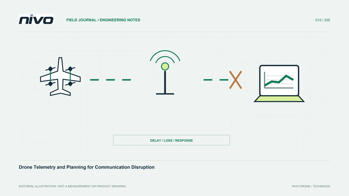
Investigate orientation-related telemetry changes through antenna type, installed geometry, diversity configuration, cable condition, and comparable observations.
Identify the antenna system rather than its outline
Similar-looking antennas can have different operating bands, polarization, radiation patterns, and connection requirements. Record the actual model and its manufacturer documentation before interpreting a link symptom. Include both airborne and ground equipment. A replacement that screws onto the connector is not automatically suitable. This establishes which installation assumptions are supported and prevents a generic image or informal nickname from becoming the basis for an RF-system decision.
Connect orientation with the observed flight phase
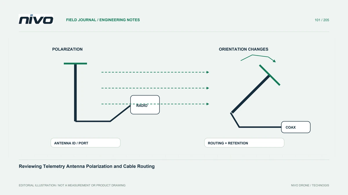
Signal behavior can change as aircraft attitude and relative direction change. Compare the symptom with turns, ground-station position, and antenna orientation rather than distance alone. Note surrounding structures and personnel near the ground installation. A repeatable orientation-related pattern suggests a useful investigation, but does not independently identify polarization mismatch or obstruction as the cause. Preserve both affected and unaffected intervals so the comparison remains interpretable.
Review diversity as an installed arrangement
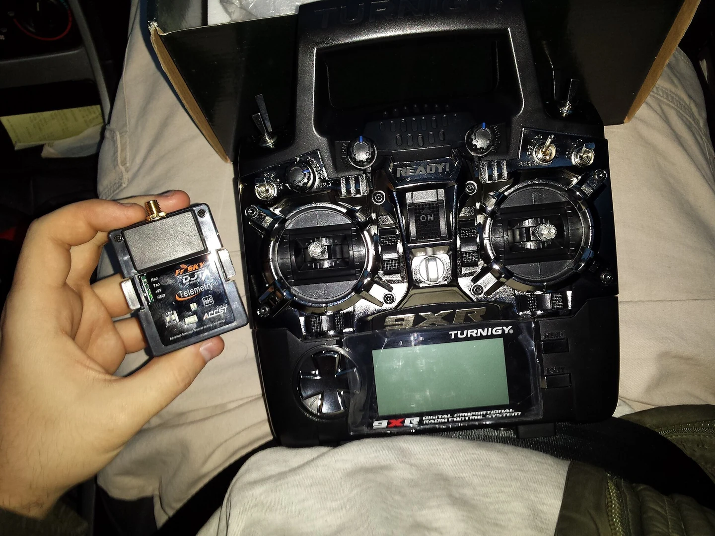
Where supported, antenna diversity depends on the modem, ports, antennas, and their documented arrangement. Two visible antennas do not prove every intended diversity function is configured or working. Confirm the relevant hardware and available status information. Do not duplicate another system's antenna angles without checking applicability. The assessment should explain what each installed element contributes and which evidence would reveal a disconnected or incorrectly substituted part.
Inspect the cable and connector path
Coaxial cable, adapters, connector condition, strain relief, and routing are part of the antenna system. Record recent replacements or tight bends and compare the installed arrangement with its accepted reference. Follow the manufacturer's handling instructions rather than improvising powered tests. A good antenna cannot compensate for every fault elsewhere in the path. Preserve removed parts where they may help distinguish mechanical damage, connection problems, or an unsuitable substitution.
Use controlled comparisons without range promises
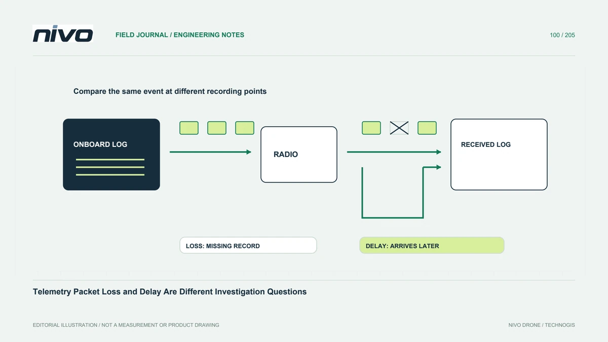
Define the question, configuration, traffic conditions, and observation method for any approved evaluation. A changed signal indicator is not equivalent to verified command-and-telemetry performance. Consider packet loss, delay, and relevant system behavior together. Do not infer a universal operating range from one favorable location or modify transmission settings without the required technical and operating review. The purpose is evidence about the installed arrangement, not an impressive distance claim.
Preserve the accepted geometry
Keep photographs, antenna identities, modem configuration, cable references, and the evaluated conditions in one installation record. Explain which later changes require renewed assessment. Ground crews should reproduce the arrangement without relying on a remembered antenna pose. This gives NiVO support a practical basis for troubleshooting orientation-related communication issues while keeping radio-system conclusions bounded by actual evidence and the aircraft's documented operating process.