Drone Telemetry and Planning for Communication Disruption
Understand telemetry functions, ground and onboard records, equipment placement, status information, and configuration-specific planning for a disrupted communication link.
Understand each communication function
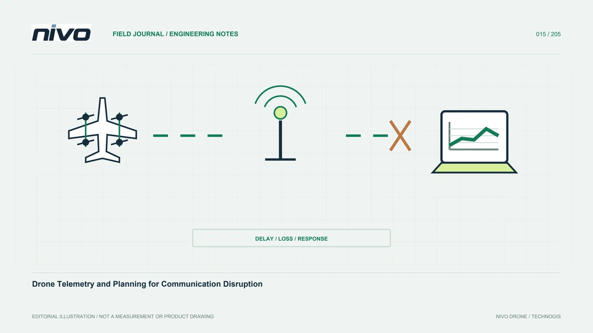
A drone may use different links for control, telemetry, video, and sensor information. These need not share one device or path. Draw the actual arrangement before discussing range. Identify airborne and ground equipment and what each connection carries. A visible video feed does not prove every control or telemetry function has the same status. This distinction improves monitoring and troubleshooting. It helps the team report which information changed instead of describing every communication issue as one undifferentiated lost signal without identifying the affected function.
Range is not an isolated number
Read advertised range with its configuration and test conditions. Environment, obstacles, antenna arrangement, and placement matter. Do not approve a plan solely by comparing map distance with a catalogue value. Use aircraft and communication-system limits and procedures. Review site conditions and relevant indicators. A successful trial in one situation does not establish every future operating limit. Evidence must identify what was tested before it informs production work. Keeping this context prevents a demonstration figure being silently converted into a universal planning assumption.
Review the ground arrangement
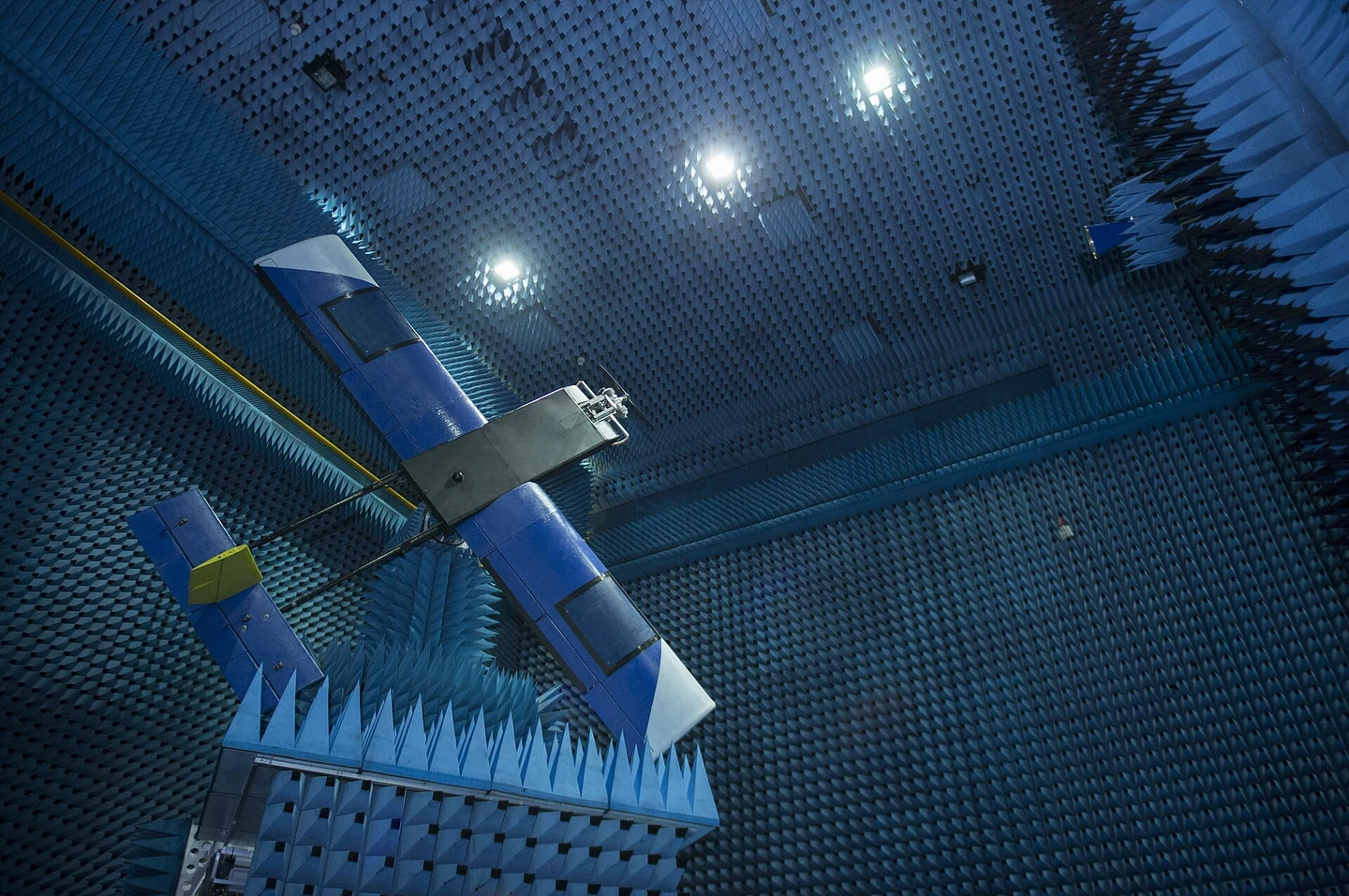
Ground-station placement belongs in the operating-site plan. Review obstacles, access, visibility, and cables according to system documents. Moving equipment during a mission can change the assessed state. Define who handles it and how changes are communicated. Do not add cables or amplifiers without technical review. A convenient layout may differ from the accepted arrangement. Record it so post-event analysis does not depend on memory after packing. Consistent identification of the ground equipment also helps support staff distinguish configuration differences between field teams.
Inspect antennas and their connections
Use the specified antenna, orientation, mounting, and connection arrangement. Presence on a connector is not enough. Check identity and reportable condition changes, and do not substitute similar-looking equipment without integrator approval. Record transfers between units. Names matter when several antennas are installed. This article provides no universal installation distance or orientation because requirements depend on the system and aircraft. The practical goal is to keep the accepted arrangement recognisable and traceable, including after transport or a repair that involved removing communication equipment.
Know what the indicators mean
Ground stations may show several link-quality values. Operators need their meaning, source, and limitations. One indicator is not a guarantee of complete information. Review messages and event timing. Training examples can align terminology so a report says more than signal decreased. Distinguish communication state, application display, and recording behaviour. Unexplained changes need the operator procedure and technical assessment rather than improvised settings. A precise description makes follow-up more useful and reduces the temptation to interpret a familiar-looking display without checking its actual meaning.
Keep lost-link planning configuration-specific
The response to disruption depends on the installed configuration and settings. Use a reviewed plan linked to the aircraft, site, mission, and system state. A general article cannot define actions or parameters for every model. Document responsibilities, observations, and approval before use. Default settings are not automatically appropriate to a project. Changes need suitable review and tests with revisitable evidence. This ensures the team knows the accepted response of its actual system instead of assuming a feature described in general autopilot documentation is already configured.
Separate display gaps from recording gaps
Missing ground information may not have the same consequences for onboard or sensor recordings. Understand where each record is stored. After an event, collect relevant files and compare timelines using the procedure. Do not fill a ground-log gap with speculation about aircraft state. Equally, one complete file does not prove every communication function worked normally. State what each source shows and what remains unknown. This supports a targeted investigation and avoids discarding useful evidence simply because another record is incomplete or unavailable.
Plan tests rather than improvising
Communication-related testing must follow an approved plan and operating limits. Specify objectives, configuration, evidence, and acceptance criteria before starting. Do not deliberately create disruption during production work merely to discover behaviour. Separate acceptance from routine survey acquisition. After hardware or software changes, consider whether older evidence still represents the system. A controlled process connects documented functions with reviewed behaviour for the actual configuration. It also protects the survey schedule from becoming an unplanned engineering experiment with unclear responsibilities or missing test records.
Use event records to improve the system
Capture time, configuration, location conditions, and operator observations for relevant disruptions. Link logs and follow-up checks. Do not assume a cause simply because a component changed recently or the site appears distant. Separate hypotheses from supported findings. Technical results may improve layout, documentation, training, or components. Communication planning then extends beyond a range claim into an operational system that can be assessed. Keeping the evidence with fleet records allows the next team to understand both the accepted arrangement and any limitations still under review.
Illustrative case: distinguishing communication functions during review
Consider a hypothetical training discussion about a mission recording that contains an unexpected gap in ground information. The video record continues, and a participant assumes that all communication functions must therefore have remained normal. The instructor asks the team to identify the actual control, telemetry, video, and recording paths in the accepted configuration. Their diagram shows why evidence from one function cannot automatically describe another. The reviewer then locates the relevant onboard files and compares timing with the ground record, explicitly noting what each source can and cannot establish. No deliberate interruption is created during production work to reproduce the event. Any further functional assessment is assigned to an approved test plan with responsible personnel and defined evidence. The field layout and antenna identities are retained as context rather than declared causes without investigation. This is an illustrative scenario, not a real lost-link incident. Its useful outcome is a precise report about the affected information and the remaining uncertainty. It also checks whether the documented response plan actually belongs to the current aircraft configuration, preventing a general autopilot feature or an old setup from being mistaken for an accepted operational arrangement.
A ground-recording issue and an aircraft communication issue may require different investigations, so the review defines which hypothesis each proposed check addresses. It does not choose a remedy merely because the same word, signal, was used in the initial report. The handoff includes the system diagram, identified record sources, event timeline, and approved follow-up responsibilities. A competent reviewer can then judge whether the evidence supports closure or further assessment. This preserves uncertainty honestly while still making progress, rather than replacing a missing record with either an unsupported reassurance or an equally unsupported claim of aircraft malfunction.