Ground, Grid, and Slope Distances in Survey Deliverables
Distinguish measured slope distance, horizontal ground distance, and projected grid distance before comparing drone maps with design drawings or field measurements.
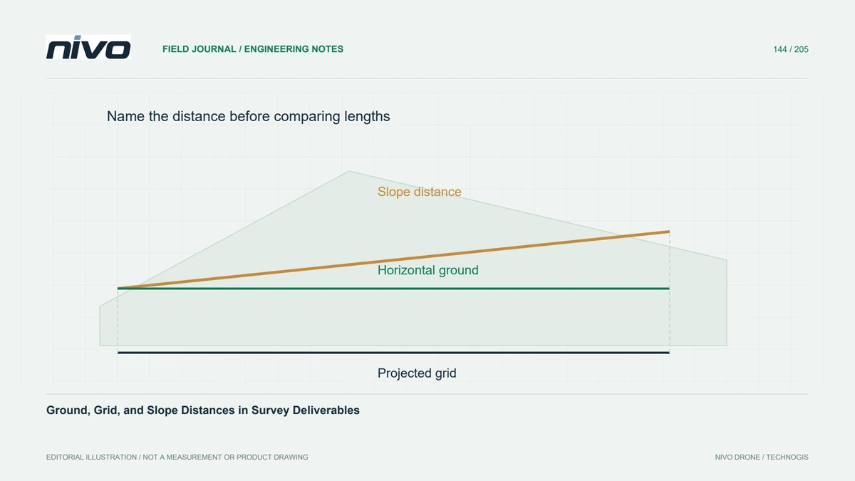
Name the distance being compared
A line measured along a sloping surface, a straight slope distance between endpoints, a horizontal ground distance, and a projected grid distance are different quantities. A GIS measurement can also use an ellipsoidal calculation rather than planar coordinates. Identify the quantity in each source before diagnosing a mismatch. Similar units and coincident endpoints do not establish that two reported lengths should be identical.
Separate slope reduction from map projection
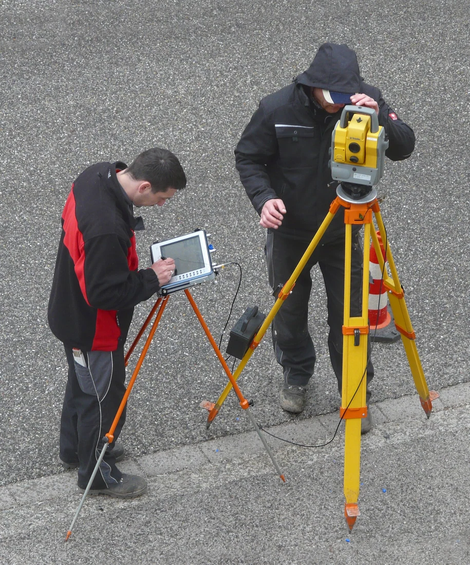
Reducing a slope distance to a horizontal quantity addresses elevation difference between endpoints. Relating a ground horizontal distance to a map grid also involves the projection and elevation context. These are separate steps. Do not use a generic percentage adjustment to reconcile them without understanding the reference surface and survey method. Retain the original observations and the definitions used by the field instrument.
Confirm the coordinate workflow
Confirm whether the project uses an established projected reference system, a documented local engineering system, or coordinates already adjusted for a specific ground convention. Reapplying an existing correction can introduce another error. Inspect control records and software job settings rather than guessing from coordinate magnitude. A map that overlays correctly with imagery may still carry a distance convention different from the construction drawing.
Use factors with a stated direction
Where a combined factor is appropriate, document its definition, location or applicable area, height assumptions, and direction of use. A multiplier from ground to grid is not numerically interchangeable with its reciprocal. Check an explicit worked conversion using the project's own data. Over an extended corridor or changing elevations, evaluate whether a single factor remains adequate for the intended tolerance.
Check a real baseline and wider extent
In a hypothetical highland access project, compare a verified field baseline with the corresponding endpoints in the delivered map. First reconcile units, slope reduction, reference system, and any local transformation. Then inspect additional baselines across the site's extent to distinguish a systematic scale effect from local measurement problems. Do not stretch the dataset to one convenient line while ignoring its effect on other control locations.
Hand over an explicit distance convention
Deliver coordinate definitions, distance conventions, applicable factors or transformation instructions, and checked baseline examples with the map. State which lengths in tables and drawings are planar, ellipsoidal, horizontal ground, or three-dimensional. Acceptance should demonstrate consistent interpretation across field and office tools. Resolving distance definitions is a survey-control task; changing stored coordinate precision or adding decimal places cannot solve an incompatible reference convention.