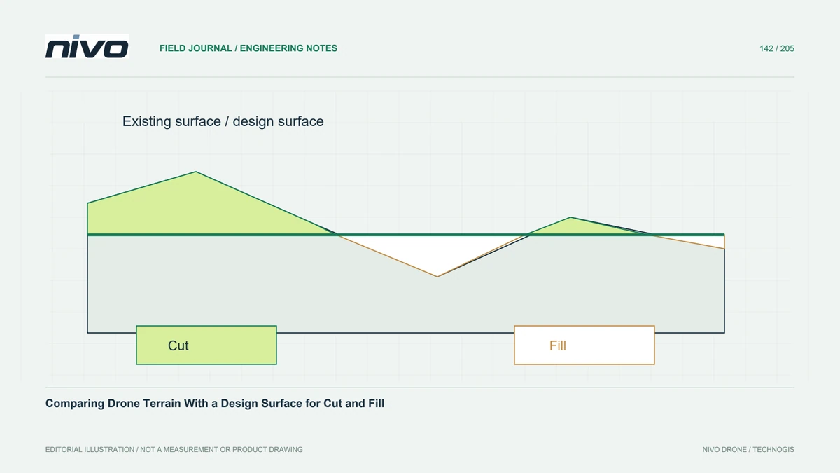
Comparing Drone Terrain With a Design Surface for Cut and Fill
Prepare compatible existing and proposed surfaces, separate cut and fill, inspect coverage and design revisions, and report volumes with clear modelling assumptions.
Identify the two surfaces precisely
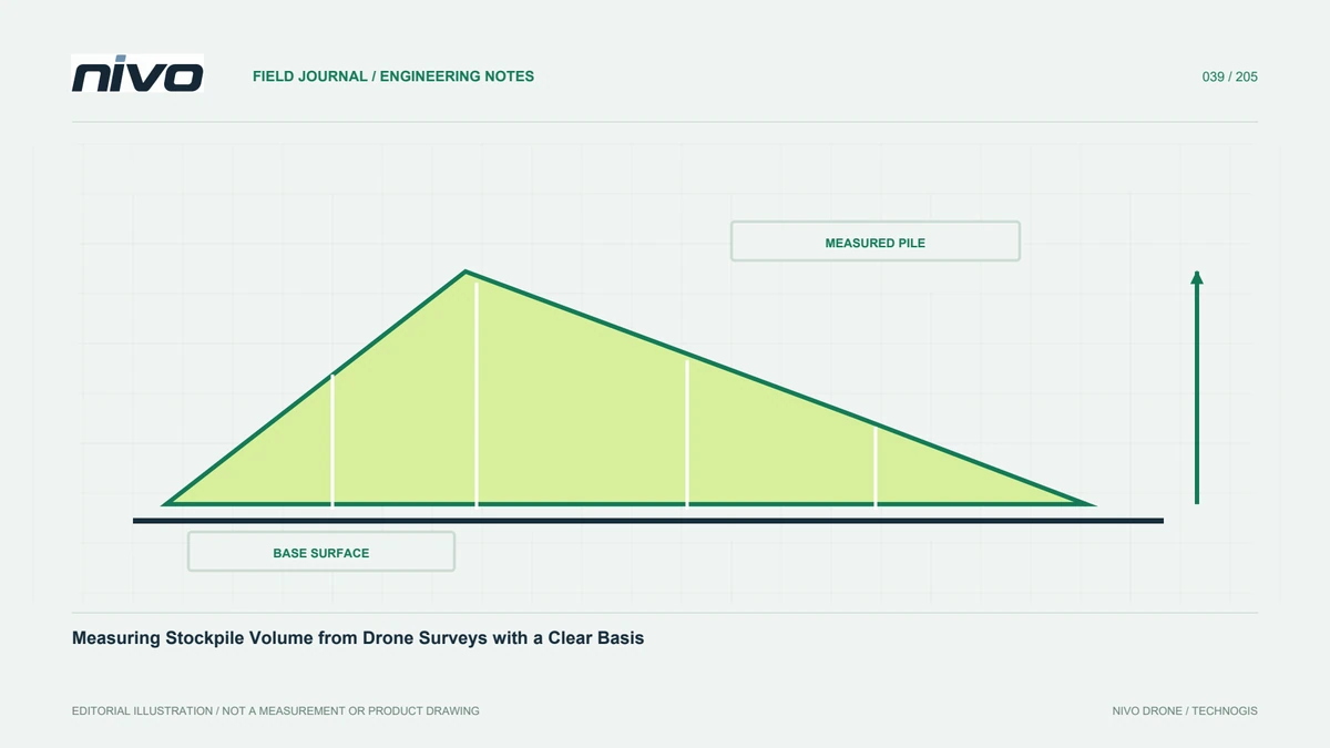
Cut-and-fill comparison asks how an existing ground surface differs from a proposed design. It is distinct from measuring a stockpile above an assumed base. Confirm the survey date, ground interpretation, design revision, and project boundary before calculating anything. An outdated grading plan can produce a mathematically correct volume that answers the wrong construction question, so version agreement is the first acceptance check.
Reconcile references before subtraction
Both surfaces need compatible horizontal coordinates, vertical references, and units. A constant height-reference mismatch can dominate the result even when the maps overlap perfectly in plan view. Check several known design levels against survey control and confirm whether structures or vegetation were removed appropriately. Do not align surfaces by an arbitrary vertical shift merely to make the resulting earthwork balance look plausible.
Define the calculation footprint and grid
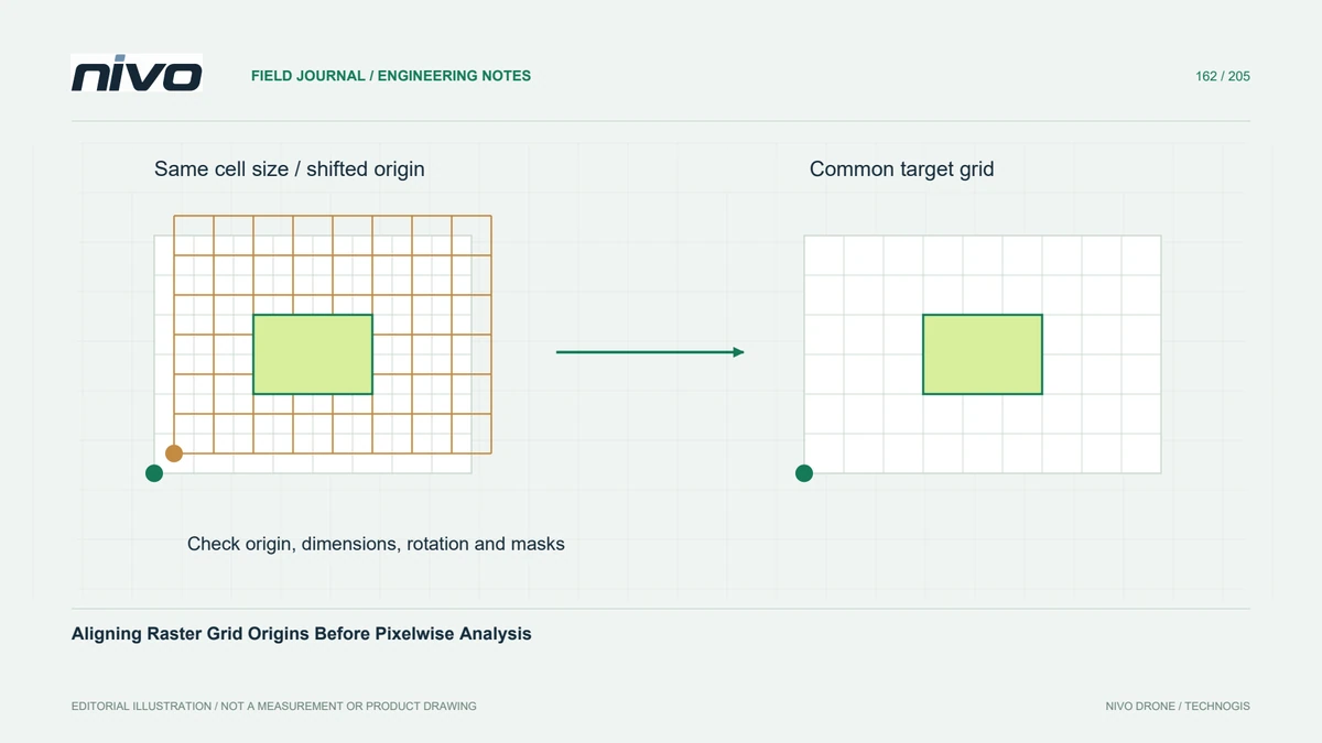
Use an agreed footprint and a documented representation, such as compatible raster cells or a suitable surface model. Inspect how missing observations, design limits, and cells partly crossing the boundary are handled. Grid resolution influences the representation of small features, while interpolation can create unsupported areas. A finer output grid does not supply additional evidence where the survey or design surface is absent.
Keep cut and fill separate
Define the sign convention explicitly and report excavation and placement volumes separately. A near-zero net balance can conceal large quantities of both. Inspect the difference map and representative sections to confirm that positive and negative areas match the intended geometry. Keep the arithmetic reproducible, including cell areas or surface integration settings and any excluded regions that affect the totals.
Test revisions and unsupported areas
In a hypothetical industrial platform project, compare the current design with a superseded revision over the same observed footprint. Review the corners of benches, drainage transitions, and areas where the survey coverage ends. Calculate a small independent check area and compare it with the main workflow. If reasonable modelling choices materially change the total, report a sensitivity range and explain the responsible geometry.
Report geometry rather than material logistics
Deliver the two source versions, footprint, reference systems, calculation settings, separate cut and fill, and an annotated difference map. Identify exclusions and areas needing supplementary survey. These are geometric in-place comparisons; converting them into truck movements, compacted quantities, or material balance requires additional project-specific assumptions. Acceptance should establish a traceable surface comparison before those operational factors are introduced.