LiDAR Boresight and Strip Alignment: Checking Consistency between Flight Lines
Connect installation geometry, trajectory, timing, and strip assessment so a LiDAR cloud does not conceal doubled surfaces or unsupported geometric corrections.
Investigate why neighbouring strips differ
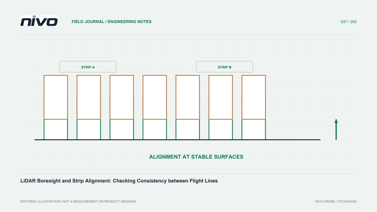
Several LiDAR lines may observe the same place. When combined, stable surfaces should agree within the quality required for the project. Systematic differences can arise from installation orientation, component offsets, trajectory, time synchronisation, or other parts of the measurement chain. A subtle top-down mismatch may become obvious as multiple roof or ground layers in a profile. Separate points by line identity and select stable objects for review. Do not apply adjustment merely to make one scene look tidy. The objective is understanding the cause while preserving a defensible connection to the reference framework.
Treat boresight as a system relationship
Boresight describes relevant orientation relationships between measurement components, such as the laser sensor and orientation unit. Its determination must follow suitable system documentation and a traceable procedure. Installation changes, impacts, or maintenance may justify checking it again under the equipment's requirements. Record sensor identity, mount, configuration version, and mechanical history. Do not copy another unit's values, since its physical relationship may differ. Qualified personnel should assess the system and test conditions. This article concerns quality management; detailed calibration manoeuvres and settings remain governed by the actual equipment manual and approved operating procedures.
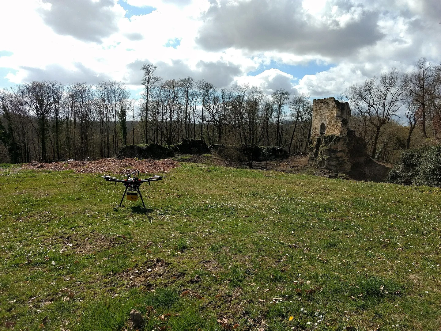
Document physical component offsets
Positions and directions between the GNSS antenna, IMU, and sensor influence transformation of measurements into map coordinates. Lever-arm measurement requires explicit axes and reference points. A sign or origin mistake can create confusing patterns. Preserve an installation sketch and measurement method rather than an unexplained table. Check configuration consistency after removing and reinstalling a payload. If a mount permits movement, the procedure must explain how repeatability is maintained. Mechanical records help investigate a change in strip behaviour even when processing settings appear unchanged, preventing a genuine installation difference from being treated as a purely computational problem.
Check trajectory and timing first
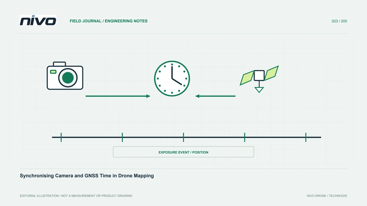
LiDAR observations depend on position and orientation through time. Review solution continuity, relevant quality records, interruptions, and known changes before attributing strip differences to one calibration value. Confirm that the trajectory file belongs to the capture session being processed. An incorrect file is not legitimately repaired by local adjustment alone. Preserve original inputs and trajectory-processing history so alternative solutions can be compared. A structured sequence distinguishes fundamental input problems from smaller discrepancies that an appropriate strip-alignment stage is intended to address, reducing the risk of using flexible correction to conceal a preventable source-data mistake.
Choose appropriate comparison surfaces
Moving objects, water, and wind-affected vegetation are poor foundations for assessing strip geometry. Select stable surfaces sufficiently observed by both lines and consider slope, orientation, and occlusion. Profiles in several directions can reveal different error patterns. Do not judge the entire site from one convenient roof. Distribute checks over relevant areas, strip edges, and flight joins. Save locations and surface identities so another reviewer can repeat the comparison. A consistent sample set also allows before-and-after assessment without selecting new examples simply because they make a chosen adjustment look more successful.
Separate relative consistency from absolute accuracy
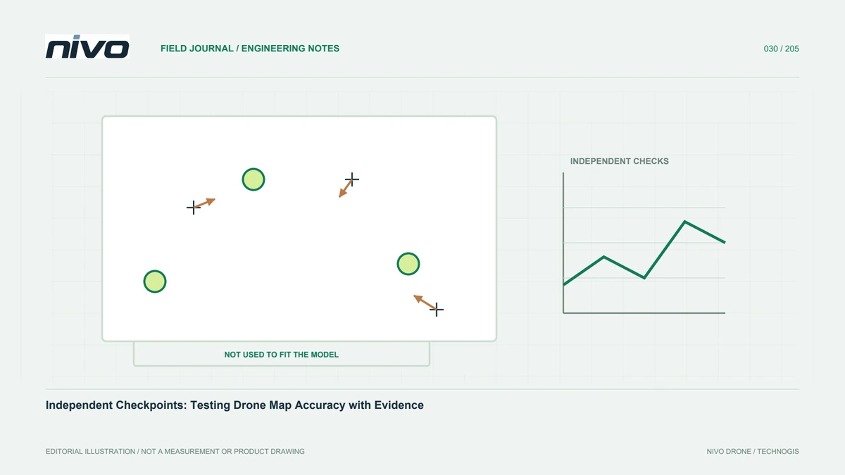
Mutually aligned strips may still share an absolute coordinate shift. Internal agreement therefore needs a separate test against suitable independent references where position is part of acceptance. Strip alignment does not replace control or accuracy assessment. Report interstrip consistency and checkpoint performance separately. Explain the role of surfaces used to constrain an adjustment; they cannot quietly become independent proof of that same adjustment. Users need to know whether evidence concerns internal dataset shape or its placement in the project framework, since these are different aspects of product suitability.
Apply adjustment through controlled decisions
Define adjustable parameters, observational support, and acceptance criteria before running correction. Keep configuration and result versions. Avoid perfecting a small area while worsening the rest. Recheck surfaces, block boundaries, and independent references afterwards. An excessively flexible correction can hide measurement problems through implausible deformation. Experienced personnel should judge whether changes fit the system's physical behaviour. The purpose is improved consistency within a defensible method, not making every statistic attractive without explaining how the correction relates to actual sensor geometry and observations.
Preserve calibration and review history
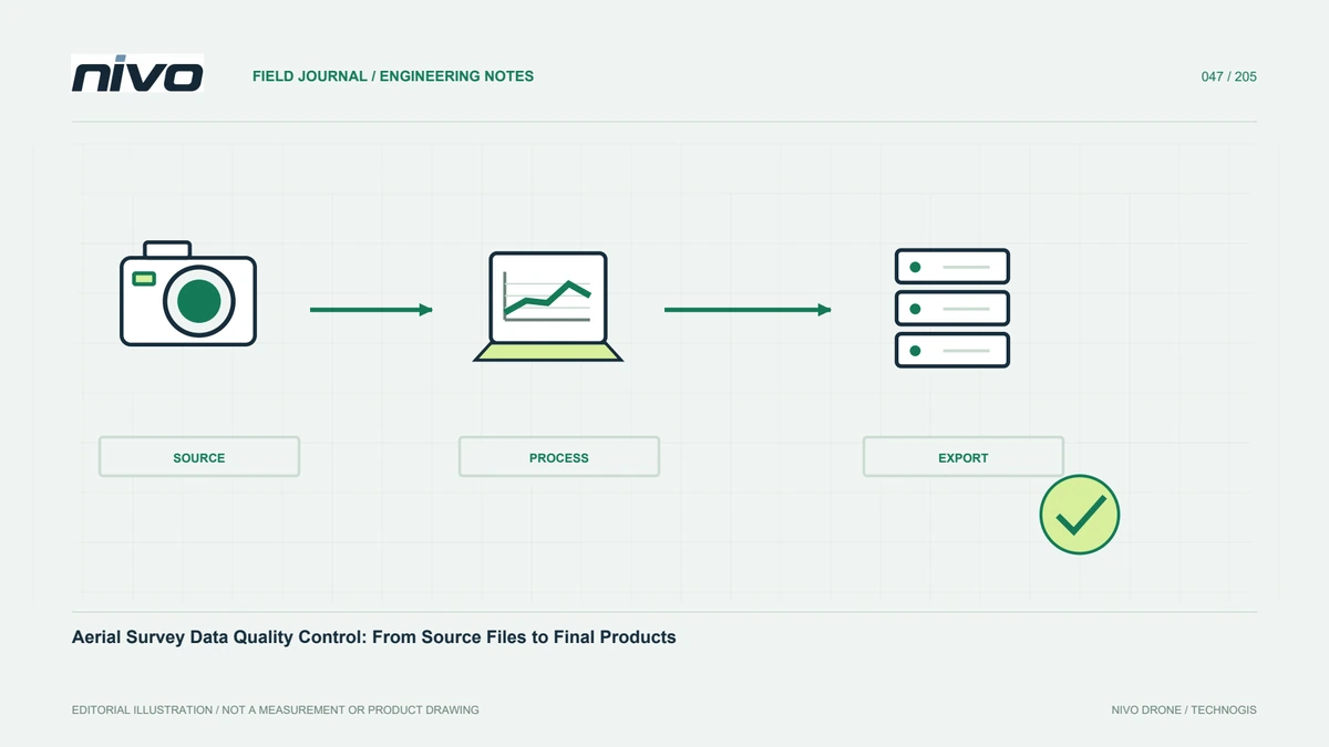
A quality package should identify equipment, installation, session inputs, trajectory, adjustment method, and results before and after correction. Include profile examples and a map of comparison locations. Record conditions that make certain areas unsuitable for assessment, such as moving vegetation or site changes. Link configuration changes to affected dates and sessions. This supports fleet management and comparison between projects without guessing from filenames. It also allows differences in derived products to be traced back to the relevant cloud version and adjustment stage instead of assuming that all versions share identical geometry.
An example involving a doubled roof
If a stable roof appears layered at a strip join, separate points by line and check whether the pattern occurs elsewhere. Review trajectory, timing, and installation before correction. After a justified improvement, evaluate locations not used to fit the adjustment and check absolute references. Retain the earlier version for comparison. In a NiVO LiDAR integration discussion, this keeps attention on measurement evidence. A clean preview is desirable, but project acceptance also needs method records, geometric review, and an understandable explanation of the resulting quality and its limits.
Illustrative scenario: strip differences after reinstallation
Consider a hypothetical LiDAR team that removes a payload for transport and reinstalls it before another session. Stable roof surfaces later appear separated when points are coloured by flight line. The processor does not immediately apply an unconstrained local correction. Equipment records are checked for the actual mount, reference points, and installation procedure. Session identity, trajectory choice, and timing records are reviewed too. Profiles across several surfaces and directions prevent one convenient roof from determining interpretation of the entire project. Earlier results remain available so changes can be assessed against the same evidence rather than against a newly selected set of examples.
Qualified personnel evaluate whether the observations justify an installation or calibration investigation under documented system procedures. Any supported adjustment records inputs, permitted changes, and affected sessions. Review then includes locations not used to establish the correction. Independent references assess absolute placement separately from agreement between strips. The report distinguishes internal consistency from demonstrated positioning quality and identifies remaining limits. This hypothetical example connects mechanical history, time records, geometry, and validation. It avoids treating every doubled surface as something that can legitimately be solved by making the cloud look unified, without explaining the physical basis or checking the consequences elsewhere.
Acceptance is tied to the reviewed session configuration rather than extended automatically to every capture made by the same sensor. If another reinstallation changes the relationship, its status must be checked through the relevant procedure. The handover identifies the configuration and correction versions actually used for each block. It also separates locations used to estimate adjustments from those used to evaluate them. A recipient can therefore follow the evidence chain and avoid assuming that a visually aligned cloud proves calibration validity for an unrelated flight or mechanical setup.