Choosing Cross-Section Thickness for Point-Cloud Interpretation
Control section position, thickness, projection direction, and envelope settings so point-cloud profiles explain observed geometry without inventing a sharp surface.
Define the question before the slice
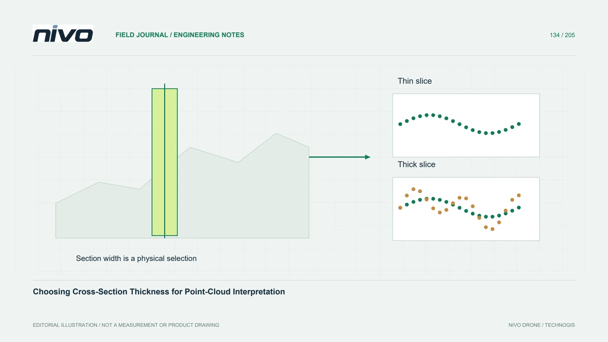
A cross-section can help examine an embankment toe, roof edge, or channel bank, but it is not simply a line drawn through a point cloud. It normally selects observations within a strip or box and projects them into a viewing plane. Define the feature and decision first, then place the section where the available observations can actually answer the question.
Separate thickness from display scale
A thin slice isolates local geometry but may contain too few points for a confident interpretation. A thick slice gathers more observations while mixing changes along the feature. The plotted line width or screen zoom does not reveal this selection thickness. Record the physical width, coordinate units, centreline position, and orientation separately from the graphic's vertical exaggeration and visual styling.
Understand projection across the strip
Points on an oblique or curving surface can spread vertically when projected from different positions within the strip. This spread may reflect real variation rather than measurement noise. Inspect the section in three dimensions and colour points by distance from the section plane where useful. Avoid fitting one sharp line through several surfaces merely because they overlap in the two-dimensional view.
Avoid overinterpreting an envelope
An extracted upper or lower envelope depends on the selected observations and the algorithm's connection settings. Long connections may bridge an unobserved gap, while tighter settings can split a profile into separate pieces. A lower envelope through vegetation is not automatically the ground. Compare it with classified points and neighbouring observations before using it as an engineering boundary.
Compare alternative section settings
In a hypothetical drainage crossing, generate several sections with the same centreline and different justified thicknesses. Compare the apparent bank position, missing areas, and any long envelope connections. Inspect the original cloud at each disputed location. Choose a width that answers the intended question without blending unrelated geometry, and explicitly mark locations where no defensible continuous boundary can be extracted.
Deliver geometry that can be reconstructed
Deliver the section line or clipping-box definition, thickness, projection convention, source version, and envelope parameters with the graphic or vector profile. Include the selected points when practical so the interpretation can be reviewed. Acceptance should establish a reproducible slice and an honest representation of gaps. A neat profile is useful communication, but its visual precision must remain tied to observed support.