Thermal and RGB Parallax: Matching the Correct Inspection Target
Check target correspondence between thermal and RGB views using original files, scene depth, viewing context, and explicit uncertainty instead of trusting screen overlays.
Separate paired recording from correspondence
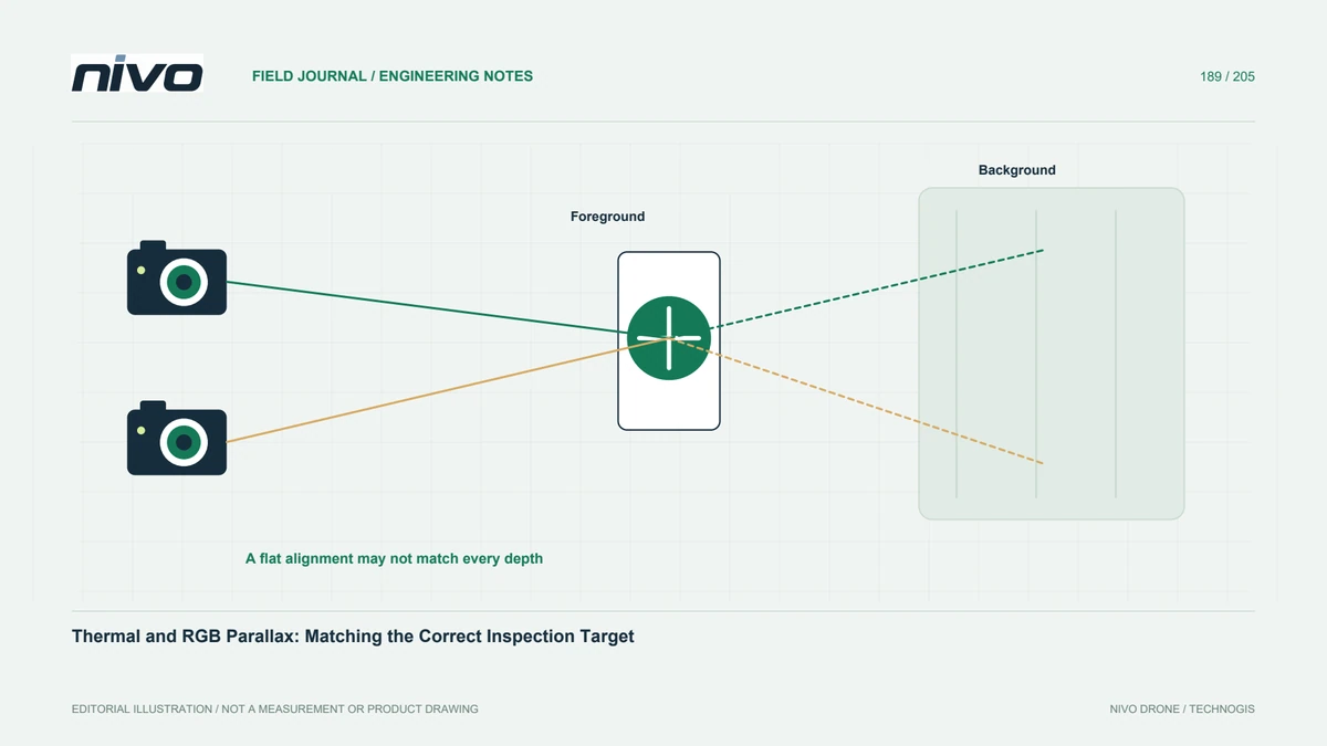
Two channels recorded at nearly the same time do not necessarily observe identical positions at every screen coordinate. Different viewpoints, fields of view, and scene depth can affect correspondence. Start by defining the target and the evidence each channel contributes. A combined display may help orientation without proving pixel-level alignment. The inspection record should establish which physical component is being discussed before a thermal pattern is attributed to a detail visible only in the RGB image.
Learn the installed viewing relationship
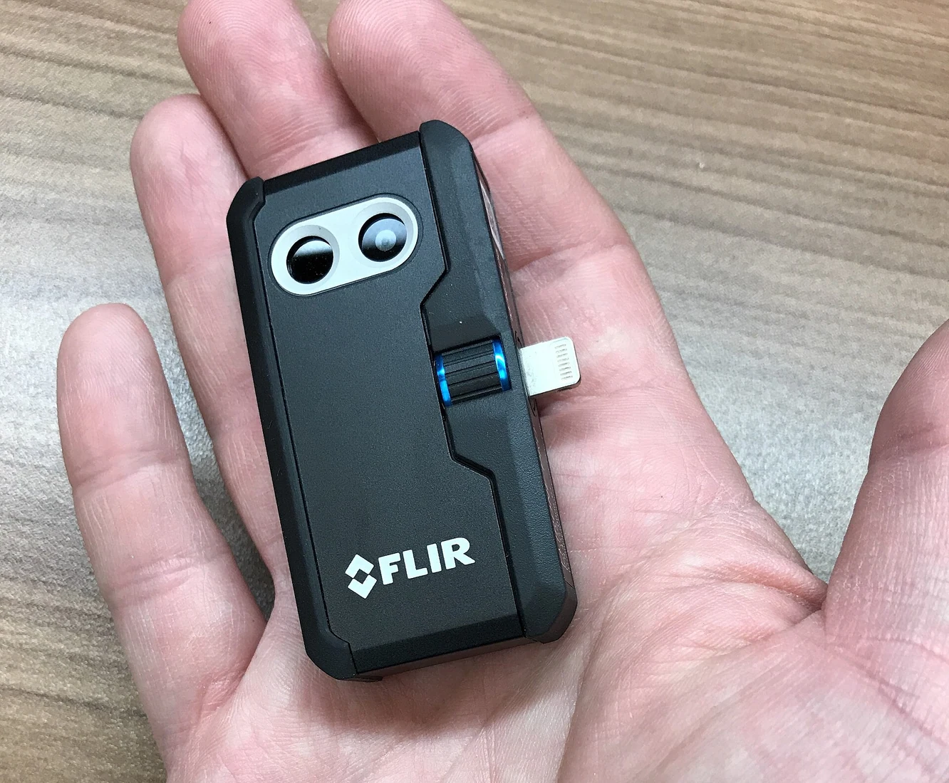
Use the actual payload documentation and representative files to understand camera layout, field-of-view differences, and any supported alignment behavior. FLIR documents alignment adjustments in its own systems; those controls must not be assumed to exist on another brand. MicaSense alignment guidance also explains why depth can complicate relationships between separate views. These principles motivate a device-specific trial, not an automatic claim that one fixed translation will align every scene and distance.
Trial targets with depth variation
Choose a controlled representative scene containing foreground and background features at different ranges. Inspect how the same recognizable object appears in both original channels. Record viewing circumstances and any applied transformation. A match that looks good on a flat wall may not remain correct around projecting equipment or an object against a distant background. Keep examples where correspondence fails, because they define the conditions under which an overlay should be treated cautiously.
Verify the finding at component scale
For each important observation, compare structural context and neighboring features in both channels. Do not rely on a crosshair or a color-blended screenshot alone. A thermal region near one bolt may correspond to another part when depth and viewpoint differ. Keep locating views and source identities with the detail. If the exact component remains uncertain, mark it for review instead of assigning a confident asset subcomponent name solely to complete the report register.
Preserve transformations and originals
Record software, alignment settings, edits, and export choices used for paired illustrations. Retain unmodified originals so another examiner can test correspondence independently. A transformed image can contain resampled or uncovered regions; make those limitations understandable. Do not crop away the very context needed to evaluate the match. Where analytical values are involved, verify how the transformation affects the intended method rather than treating visual agreement as sufficient evidence of measurement equivalence.
Accept a practical matching procedure
Ask a reviewer absent from capture to identify the intended component from a sample evidence pair. Include difficult depth cases in acceptance, not just a flat calibration scene. Document where channel matching is reliable for the task and where extra views or another method are needed. Discuss these examples during NiVO thermal-payload consultation. The useful result is a traceable component association with stated limits, without claiming universal pixel correspondence or diagnosing a fault from an unverified overlay.