Investigating Compass Interference After Drone Wiring Changes
Trace heading inconsistencies through device identity, wiring geometry, nearby materials, power-state evidence, and a documented installation review.
Begin with the changed installation
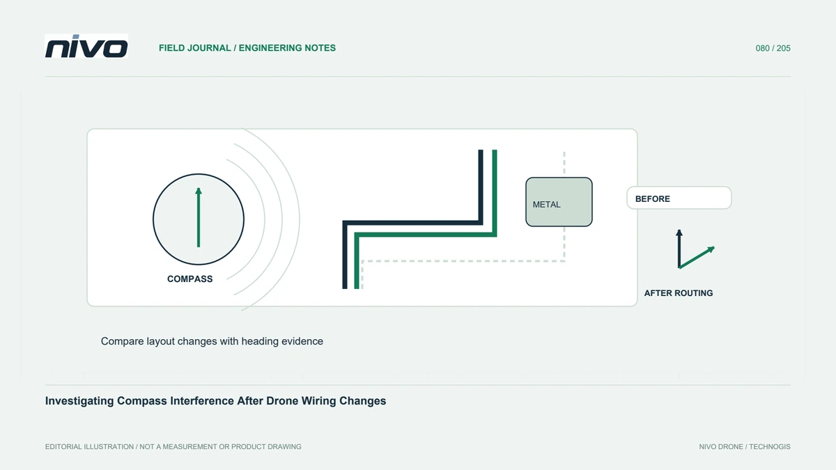
A heading inconsistency appearing after maintenance deserves a review of what physically changed. Record cable routing, power equipment, fasteners, payload mounts, and magnetic-sensor identity. A neat installation photograph does not reveal every electromagnetic influence, but paired photographs help locate differences. Establish whether the symptom follows one aircraft, a particular operating location, or a replacement component before deciding that the compass itself must be defective.
Identify the sensor actually used
Systems can discover several magnetic sensors, and the visible device name does not necessarily explain priority or active use. Read the relevant configuration and logged device identities. Distinguish an external module from internal sensors and retain their installation orientations. Do not erase unfamiliar identities simply to remove an inconsistent-sensor message. The technical question is whether the intended, documented sensor arrangement is present and behaving as expected.
Map possible interference paths
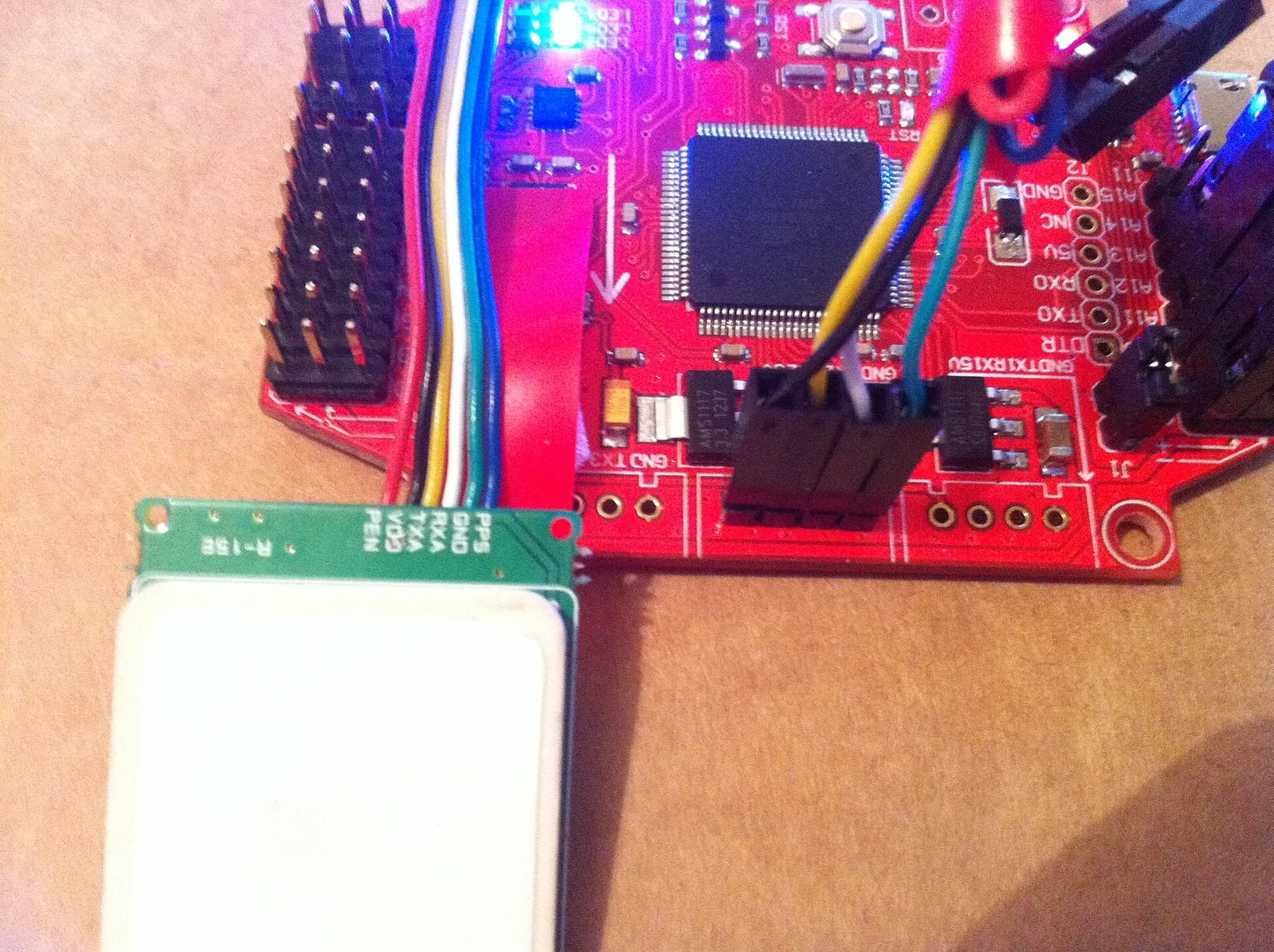
Power wiring carries current and can influence nearby magnetic measurements; surrounding metal and local equipment can also matter. Draw the relative locations rather than relying on cable color or memory. Note where conductors were rerouted or bundled differently. The diagram should distinguish aircraft-installed sources from the ground environment. It supports inspection planning without assuming that one published separation distance suits every current, sensor, and airframe arrangement.
Use approved comparisons
Any powered examination must follow the aircraft's maintenance and propulsion precautions. Competent personnel can define which operating states provide relevant evidence without improvising a test around moving machinery. Retain headings, sensor messages, current information where available, and the corresponding state. Compare repeatable observations rather than a single compass display. A correlation with equipment operation is a clue requiring interpretation, not automatic proof of a particular electrical fault.
Avoid calibration as a substitute for investigation
A completed calibration message does not show that every interference source has disappeared. First establish device selection, orientation, installation condition, and the suitability of the calibration environment. Repeatedly recalibrating beside the same unexplained influence can conceal the real question. Document the applicable procedure and its outcome. If wiring changes are proposed, review their electrical and mechanical consequences instead of moving one cable until a display merely looks plausible.
Preserve the resolved geometry
Close the finding with configuration references, installation photographs, evaluated conditions, and any remaining limitations. Link the record to the aircraft and maintenance action so future payload work does not unknowingly recreate the problem. Brief technicians on the relevant routing requirement and its reason. The outcome is a traceable installation decision that can inform NiVO support discussions, while flight approval remains grounded in the complete aircraft checks rather than heading appearance alone.