Integrating Drone Payloads: Mass, Mounts, and Centre of Gravity
Payload integration involves more than lifting capacity. Review centre of gravity, mounts, power, vibration, wiring, timing, and configuration acceptance evidence.
Capacity starts the discussion
A payload rating helps shortlist devices, but it does not define the whole integration task. A camera below the limit still needs review of its mount, cables, power, field of view, and mass distribution. Supporting equipment is easily missed when only the sensor body is weighed. List everything actually installed and distinguish measured information from estimates. Then assess the configuration against aircraft documentation with the responsible technical team. The question is whether the complete arrangement is suitable, not merely whether one device fits under a catalogue number.
Treat centre of gravity as a configuration state
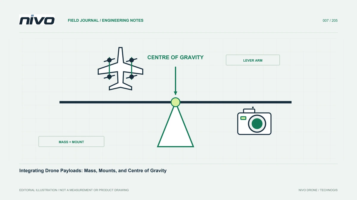
The centre of gravity concerns the whole aircraft. Battery changes, moved mounts, and communication equipment can alter the state requiring assessment. Limits and checking methods depend on the model. Document the arrangement when it is accepted. Installation photographs help but do not replace required measurements. Recheck the relationship after changes. Similar-looking setups should not be assumed equivalent. A configuration record allows the team to confirm which actual arrangement the acceptance evidence represents before using it for a new payload or project.
Review the mount as part of measurement
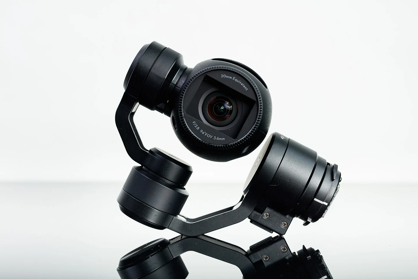
A mount maintains the geometry between sensor and aircraft. Where position and orientation matter, a change in that geometry can affect the explanation of results. Review joints, locking, and repeat installation under the integrator procedure. Ask how the sensor position relative to GNSS is recorded. Tightness alone is not evidence of complete suitability. Consider vibration, access, and maintenance. Orientation marks should help staff identify correct installation without guessing from shape, particularly when a device is removed repeatedly for transport or used by different personnel.
Check viewpoint and orientation
The sensor must observe the intended environment. Review whether structure, cables, or mounts obscure the view. For a gimbal, assess movement and cable paths. For a directional sensor, orientation changes may affect coverage. Use an appropriate functional check and retain sample data. Successful recording does not prove every part of the image is usable. Shadows, reflections, and blocked areas may only become obvious during detailed inspection. Confirm that the accepted viewpoint supports the actual mapping or inspection task rather than merely producing a visible image.
Plan electrical requirements and connections
Account for both the sensor and supporting devices. Review voltage, power demand, connectors, and startup behaviour. Confirm that the supply path is approved for the configuration. Cable routing should avoid pulling on connectors or interfering with assembly. Do not substitute a connection because it looks compatible. Record the device relationships and label cables clearly. A simple diagram improves checks and reduces mistakes during removal or staff changes. Electrical integration needs the relevant documentation and competent personnel, not an improvised field solution to an unexplained connection problem.
Consider vibration and cooling
The mounting environment can influence data quality and equipment condition. A mount suitable for one sensor may not suit another. Check whether manufacturer cooling and installation requirements are met. Evaluate vibration using appropriate evidence, including images or sensor data and available system records. Adding damping material without assessment may change stiffness or orientation. The objective is a configuration whose behaviour can be explained and maintained, not a device that simply appears quieter during a ground inspection without evidence about its operation in the accepted system.
Connect sensor data with time and position
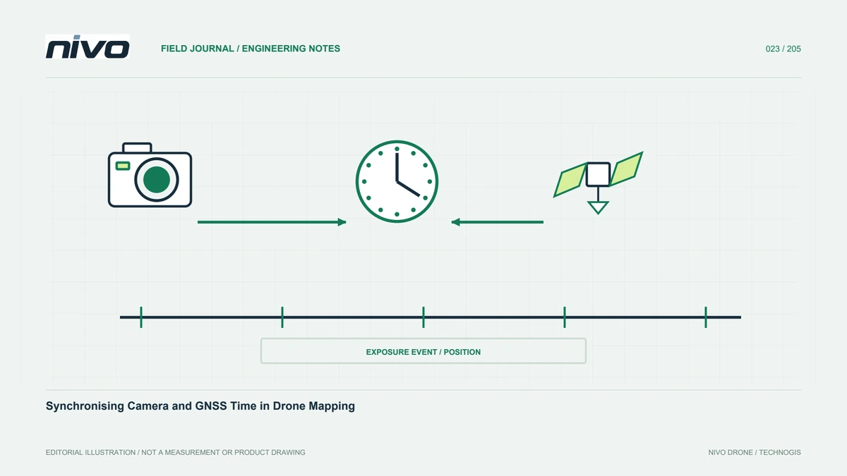
Recorded imagery does not automatically provide complete georeferencing. Understand how acquisition events are logged and matched with position and orientation. Check names, clocks, intervals, and handling of missing records. Test examples from the beginning, middle, and end. If another application is involved, document its version and settings. A usable integration keeps the relationship between command, sensor record, and processing input traceable. It should also allow the team to recognise incomplete information rather than silently creating an apparently continuous sequence from inconsistent sources.
Accept the configuration in stages
Use a test plan approved for the aircraft and competent personnel. Separate mechanical, electrical, recording, and data-quality checks so problems can be isolated. Define evidence required before each next stage. Avoid changing multiple elements at once. Record the initial state, reason, change, and result. Acceptance must identify the actual sensor and support equipment. General support for a sensor category does not establish that the proposed arrangement has been reviewed. Evidence should relate directly to the hardware and workflow the operator will take into production work.
Manage payload changes as system changes
Where several sensors are used, provide configuration cards linking device, mount, battery, cables, settings, and checks. Operators should match the card to the installed hardware. After a change, perform the specified verification before the next job. If equipment moves between aircraft, retain its identity and history. These records help explain data differences between configurations. NiVO payload pages provide a starting point for selection, while a specific technical arrangement defines integration. Keeping those roles clear makes expansion easier without presenting every future sensor option as an already accepted capability.
Illustrative case: replacing a camera without losing configuration control
Imagine a team considering a different camera for a hypothetical mapping assignment. Its body appears to fit the payload allowance, so the initial request describes the change as a straightforward replacement. The integrator instead lists the complete installation: camera, lens, mount, cabling, storage, and supporting electronics. The reviewer checks the accepted centre-of-gravity method and the relationship between the antenna reference and sensor. The processor asks whether event logging and file matching will remain valid. No previous acceptance result is automatically transferred to the proposed arrangement. A staged review first verifies the mechanical and electrical documentation, then examines the recording workflow using representative data under the approved test process. Photographs of the installation accompany the configuration identity, but do not replace required measurements. If a cable or mount changes during preparation, that change is recorded before the next assessment. The resulting evidence explains what was actually installed and what functions were demonstrated. This hypothetical example shows why payload capacity is a screening value rather than a complete integration decision. It also gives operators a configuration card they can check when the camera is removed for transport and installed again for another project.
The project can remain with the previously accepted camera, or allow time for the proposed integration to earn its own acceptance. The distinction belongs in the schedule and deliverable description, not only in an engineering conversation. For the new arrangement, the handoff pairs the installation record with representative sensor files and the definitions used in processing. For the existing arrangement, it clearly identifies which requirement is still deferred. This prevents a physically installed device from being mistaken for a completed service capability and gives both the operator and processor the same account of configuration readiness.