DroneCAN Node Identity, Termination, and Installed Topology
Investigate DroneCAN installations through node identities, status evidence, physical topology, termination references, and documented device-specific support.
Inventory nodes before changing configuration
List the controller and each connected DroneCAN device with physical identity, firmware, function, and available node information. A familiar device name does not establish which physical unit produced a message. Preserve the discovered network state before changing addresses or replacing components. This inventory gives intermittent missing-device reports a concrete basis and prevents a newly connected spare from being assumed identical to the unit it replaced.
Understand identity and allocation
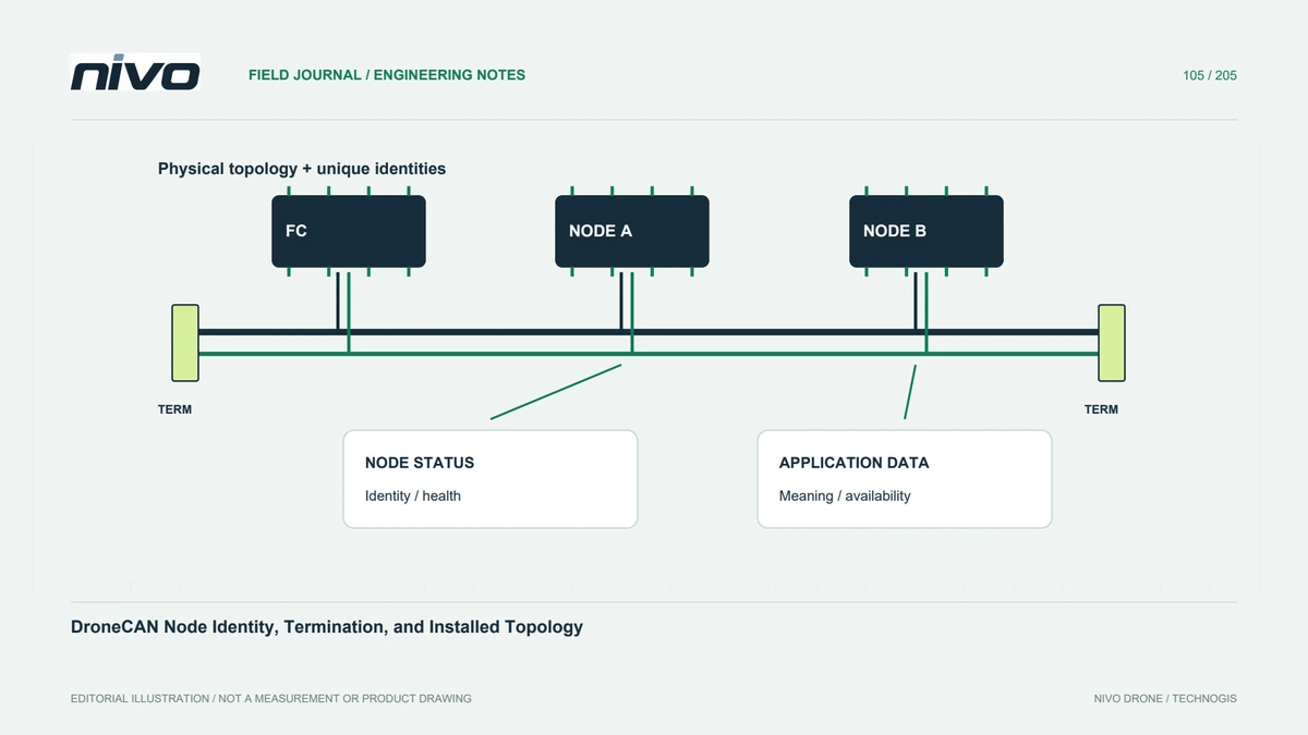
DroneCAN nodes require identities appropriate to the network, and supported systems can use different allocation arrangements. Read device and network documentation rather than assigning arbitrary values until warnings disappear. Distinguish persistent hardware identity from the node identifier observed in a session. Record expected behavior after restart. Unique and understandable identity is important because received data must remain associated with the correct sensor or actuator across maintenance and reconfiguration.
Draw the physical bus
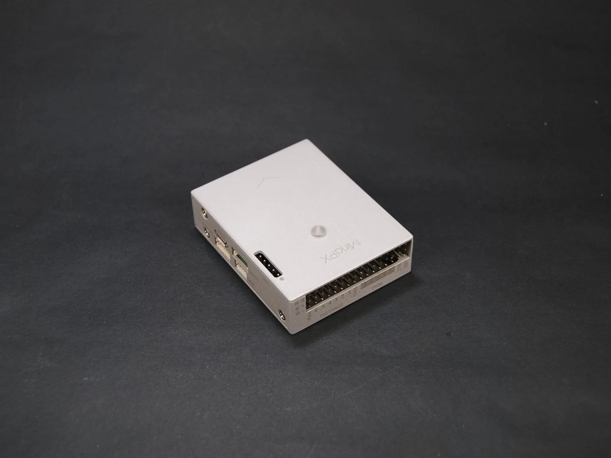
Map cable segments, junctions, connectors, power distribution, and termination according to the actual installation. A simplified software device list does not reveal every physical branch. Compare the arrangement with applicable hardware guidance and approved aircraft design. Do not add terminators merely because communication appears unstable. Correct assessment needs the location and purpose of the existing elements, along with device requirements and any changes made during recent work.
Separate node status from useful application data
A present node can report status without supplying every function expected by the aircraft. Examine the relevant application messages, device health information, and implementation support. Conversely, a missing display item can originate in the receiving configuration rather than prove a broken bus. Preserve timestamps and affected functions. This distinction guides the next check toward physical connectivity, identity, software interpretation, or device-specific behavior instead of treating every symptom as identical.
Evaluate changes with a known baseline
When a device or cable is replaced, record exactly what changed and review the resulting topology and configuration. Use approved diagnostic methods and appropriate electrical precautions. Compare startup, status, and required application behavior with the retained baseline. A single successful discovery is not complete acceptance. The evidence should show that the correct physical device supplies the intended information reliably within the conditions the technical process actually evaluates.
Keep a maintainable network reference
Store the bus diagram, component identities, allocation assumptions, termination references, software versions, and accepted checks together. Make later expansions trigger a review rather than an informal plug-in decision. This helps NiVO teams assess supported CAN peripherals without assuming universal compatibility. It also makes service communication more efficient: the technician receives an identifiable network and a bounded symptom, not simply a report that a CAN sensor sometimes disappears.