UART, PWM, and CAN: Verifying the Actual Drone Interface
Separate connector shape, electrical compatibility, signal meaning, protocol support, and application behavior when integrating drone sensors and payloads.
Start with function rather than connector shape
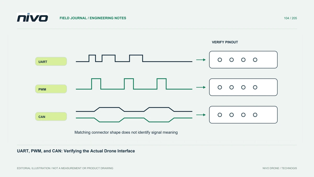
Two devices can use similar connectors while carrying different signals or electrical requirements. Identify the actual port, pin functions, supply expectations, and manufacturer documentation on both sides. UART, PWM, and CAN describe different interface arrangements; they are not interchangeable labels for a cable. A successful mechanical connection cannot approve the integration. Build an interface record before selecting adapters or assuming that familiar wire colors establish compatibility.
Separate electrical and information layers
Electrical compatibility is one question; the meaning of transmitted information is another. A serial connection does not automatically mean both devices use MAVLink, and CAN connectivity does not establish support for every application protocol. PWM behavior likewise depends on the relevant device and configuration. Document each layer explicitly. This prevents troubleshooting from jumping to software settings while an unresolved electrical or pin-definition issue remains in the installation.
Record direction and ownership
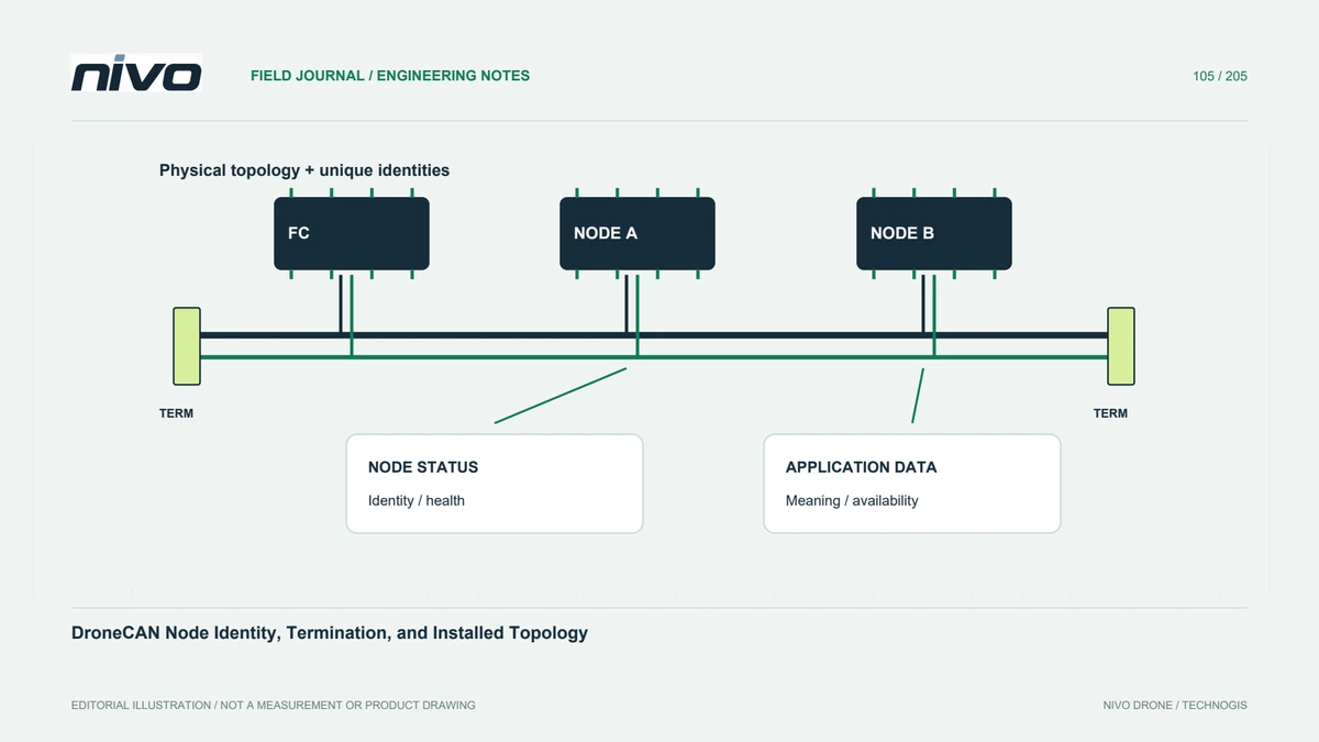
Identify which component sends, receives, commands, reports, or supplies power. Include routing and any intermediate converter. An observed status value is different from a confirmed command response. Where several devices share resources, explain their identities and roles. A clear diagram helps separate a wiring reversal, unsupported message, output-mapping issue, or application misunderstanding without repeatedly changing settings merely to see whether something starts moving or appearing on screen.
Check the documented implementation
Read the applicable aircraft, controller, and payload information for supported ports, software versions, settings, and limitations. A generic protocol standard explains capabilities, not necessarily what a particular product implements. Record any required adaptation as engineering work rather than an existing feature. Do not infer NiVO compatibility from a category name alone. The accepted interface must describe the configuration actually supplied and the evidence used to establish its intended operation.
Verify the complete information path
Use an approved test plan connecting a known input or command to the expected device behavior and recorded evidence. Keep propulsion and other hazardous functions under the applicable maintenance precautions. Confirm behavior after the documented restart or reconnection conditions where relevant. A visible message alone may prove reception without proving correct interpretation. Preserve unsuccessful observations because they can reveal whether a later change addressed the original question or merely changed the symptom.
Hand over an interface definition
Provide port identities, wiring references, electrical requirements, protocol roles, software context, and acceptance results. Keep adapters and cable revisions identifiable. A future technician should connect the approved components without reconstructing an experiment from memory. This makes NiVO payload discussions practical and reduces assumptions about plug compatibility, while leaving untested combinations clearly distinguishable from configurations with documented end-to-end behavior and an appropriate technical release.