Lever Arms: Coordinate Frames and Sign Conventions in Drone Integration
Document sensor offsets through defined origins, axes, signs, measurement endpoints, configuration ownership, and verification of the installed geometry.
Define the two physical points
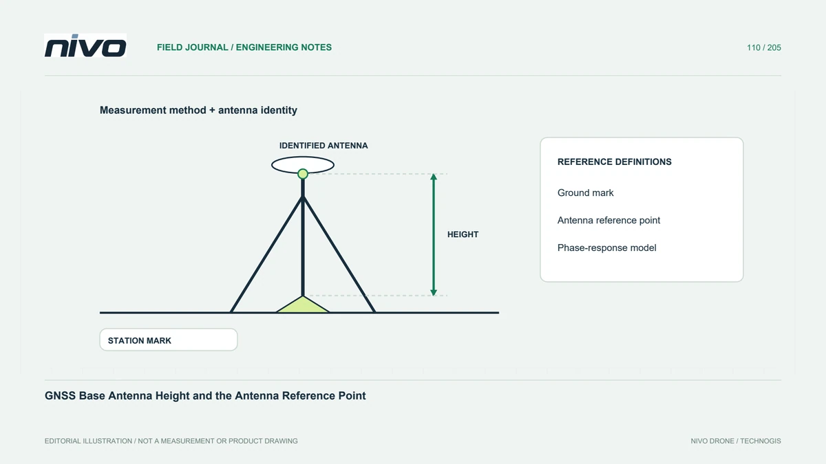
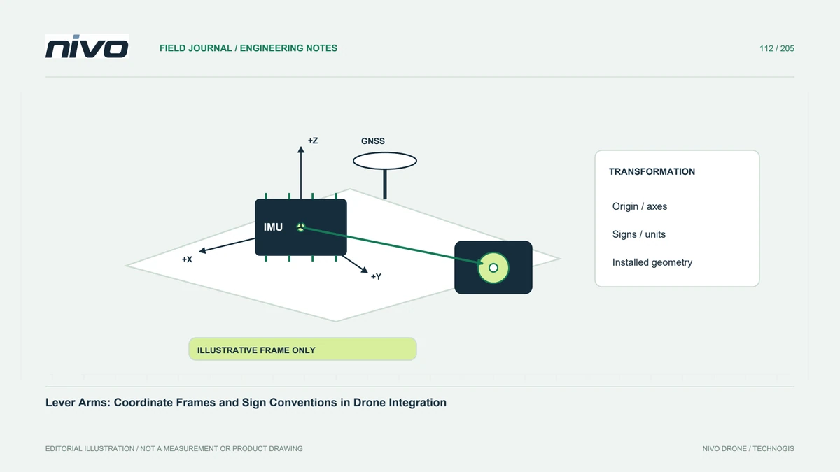
A lever arm describes a spatial relationship between specified reference points, not simply the distance between two visible housings. Identify the antenna, inertial sensor, camera, or aircraft origin relevant to the workflow. Use the actual documentation to define endpoints. A careful measurement can still be entered incorrectly if it refers to a different point from the software expects. Begin with a labeled installation sketch rather than an unexplained three-number note.
State the coordinate frame and signs
Offsets require axis directions, an origin, units, and a sign convention. Different tools or integration stages may not use the same definition. Do not transfer a coordinate triplet between them without establishing the transformation. Include arrows on the sketch and explain what positive and negative mean. This makes a small sign error easier to detect before it becomes an apparent navigation, alignment, or camera-position problem during later processing.
Measure the installed arrangement
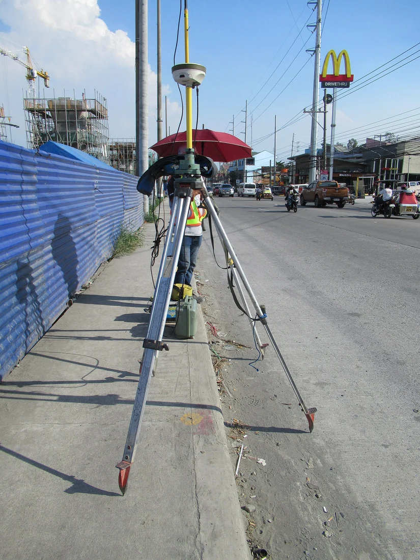
Record the method, accessible references, component identities, and uncertainty appropriate to the task. The aircraft's operational configuration matters: a removable mount or changed payload can alter the relationship. Preserve photographs and the version of the mechanical arrangement. Do not assume a drawing from another unit represents the supplied installation. Measurement evidence should let a technical reviewer understand what was physically established and what remains an estimate requiring further work.
Identify where compensation is applied
The flight controller, payload integration, GNSS workflow, and processing software can have different responsibilities for spatial offsets. Establish which stage applies which relationship and to what reference. Avoid both omission and unintended duplicate treatment. A populated field does not prove the complete chain is correct. Keep the relevant configuration and processing records together so an analyst can trace the final position back through the actual transformations.
Verify through the relevant output
Choose a validation method suited to the function the offset supports, using the approved technical process and suitable independent evidence. Internal consistency alone may not reveal every shared reference error. Examine patterns rather than forcing one result to fit by changing signs experimentally. Preserve failed checks and the reason for each revision. The objective is an explainable installed relationship, not a set of values that merely reduces one selected residual.
Control changes to the geometry
Antenna movement, controller replacement, camera remounting, or structural work should trigger review of the affected reference relationship. Keep accepted measurements, conventions, configuration, and evidence with the aircraft identity. This makes NiVO integration discussions more precise and prevents a spare component from inheriting offsets that no longer describe reality. The record should show both the accepted geometry and the conditions requiring a new measurement or validation.