LiDAR or Photogrammetry: Choosing a Method for the Data You Need
Compare LiDAR and photogrammetry through observations, land cover, colour, processing, validation, and total project effort rather than sensor specifications alone.
Start with the project question
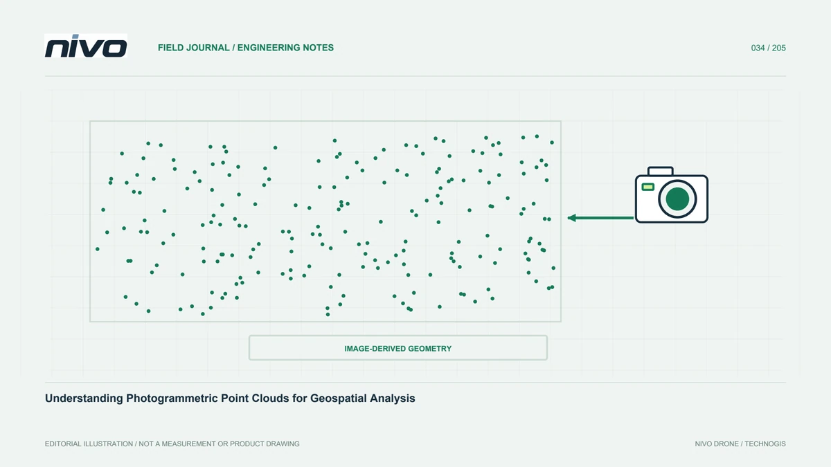
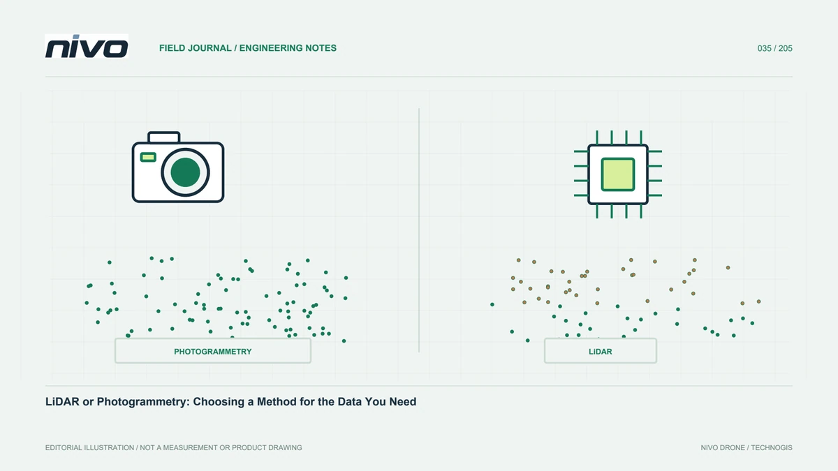
Choose between LiDAR and photogrammetry by identifying the information users need: visual mapping, ground shape, object heights, or facility documentation. Photogrammetry reconstructs visible surfaces from image relationships. LiDAR combines laser range observations with sensor position and orientation. Both can produce point clouds, but their information sources and limitations differ. Define deliverables, cover conditions, and validation before comparing equipment costs. Point count or a similar three-dimensional appearance is not enough to establish suitability. The useful comparison asks whether each method provides the observations required for a decision, and how that adequacy will be demonstrated.
Consider photogrammetry's visual strengths
RGB images supply colour and texture that many users can readily interpret. Orthomosaics reveal roads, roofs, plot layout, and visible surface conditions. Suitable imagery and geometry can also support three-dimensional reconstruction. However, visual matching becomes difficult over uniform surfaces, water, strong shadows, repetitive patterns, and moving objects. If the main requirement is a visual map of relatively open land, test photogrammetry on a representative block. Assess sharpness, feature readability, and independent checkpoints. More megapixels do not automatically establish better geometry without considering lens, acquisition distance, and reference quality.
Understand LiDAR's different observations
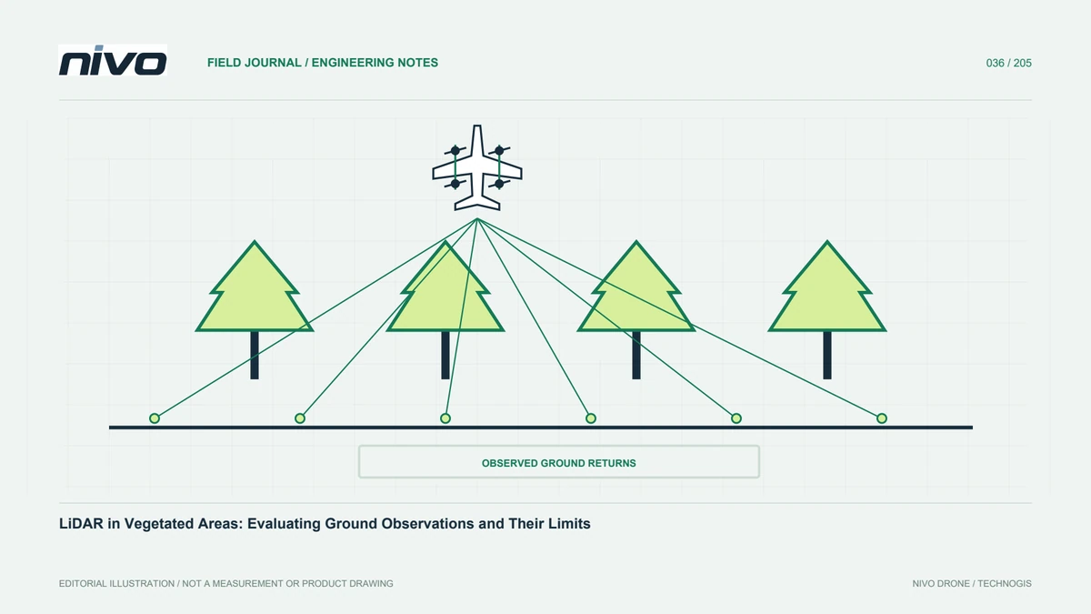
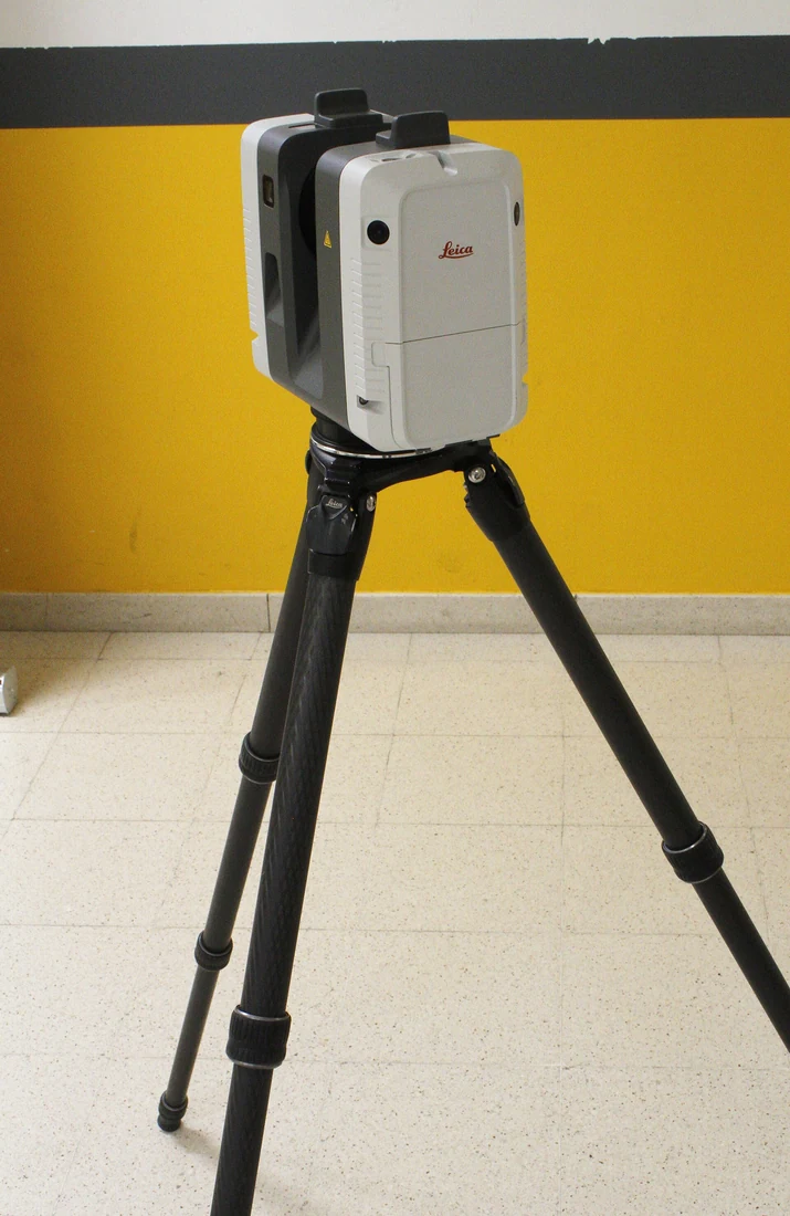
LiDAR can observe several surfaces within a scanned environment, depending on system capabilities and conditions. Some pulses may reach ground through vegetation gaps, which can support particular terrain requirements. This does not mean laser measurements always penetrate every canopy or fully observe underlying ground. Examine ground-return distribution, scanning geometry, and trajectory quality. Position and orientation integration also matter. A dense cloud does not prove correct coordinates or classification. Test the method in conditions representing the difficult parts of the project rather than transferring expectations from an attractive demonstration at a much easier site.
Compare the complete processing chains
Photogrammetry requires attention to image connectivity, camera orientation, and reconstruction. LiDAR requires trajectory, timing, installation geometry, strip consistency, and classification checks. Both still need a reference framework and independent assessment. Estimate effort from the whole workflow, not one computational stage. A LiDAR cloud available early may still need careful ground classification; a rendered orthomosaic may still contain incorrect seams. Include staff skills, software availability, and documentation support when comparing total cost. More expensive equipment does not automatically shorten production if necessary quality tasks were omitted from the original estimate.
Specify colour and attributes
Visual interpretation often benefits from consistent RGB colour, whereas some shape analyses primarily require coordinates and measurement attributes. LiDAR clouds may be colourised where a suitable camera and processing workflow are available, but colour alignment also needs checking. Intensity and return information are not interchangeable with RGB. Agree required attributes and delivery formats early. If users need both an orthomosaic and a terrain representation, combined sensors or separate captures may be sensible. Assess their additional value against a real requirement rather than adding equipment merely because it can technically generate another type of data.
Evaluate difficult conditions explicitly
List canopy, slopes, structures, cables, reflective surfaces, water, and changing activity. For each, identify possible information loss and the planned check. Both methods can have weak areas, but the causes and appearances differ. On slopes, review viewing direction and geometric shadowing; at active sites, review changes during capture. Avoid transferring conclusions between environments without testing. A representative difficult block often provides stronger evidence than a best-case demonstration. This evaluation can also identify where a supplementary survey is necessary, preventing a false expectation that either method will observe every required surface everywhere.
Estimate cost through acceptance
Include mobilisation, field references, payload configuration, flight, storage, processing, review, and corrections. Flight time alone is an incomplete comparison. Allow for recapture when weather or site conditions reduce usable information. Build scenarios around area, access, quality needs, and actual products. Simpler capture may be sufficient on open land, while a cheaper sensor choice can create additional work in difficult cover. Explain assumptions so users can see what drives cost differences. The objective is a useful, defensible result at an acceptable effort and risk, not the most sophisticated technology or the largest advertised coverage figure.
Use a fair validation comparison
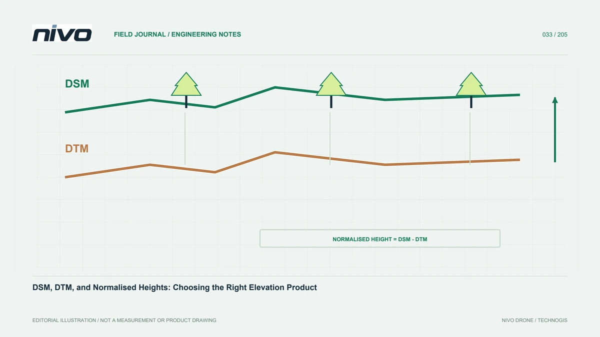
Keep area, references, surface definitions, and assessment methods compatible when comparing outputs. Comparing a photogrammetric DSM with a LiDAR DTM and calling every difference an accuracy discrepancy is misleading. Separate visual quality, completeness, relative precision, and absolute accuracy. Use independent references suitable for the relevant conditions. Preserve profiles and maps of missing information. Where one approach performs better for a task, explain the conditions supporting that conclusion. Such evidence can guide a NiVO payload discussion without implying that one configuration is superior for every possible survey environment.
A mixed-site decision example
Consider open land, dense plantation, and buildings where users need an overall visual map plus ground information under vegetation. Test RGB for interpretation and LiDAR for the particular terrain requirement, then assess whether their combination covers the need. If ground observations remain insufficient, plan supplementary measurements instead of silently filling the gap. Document agreed products and limitations. A NiVO configuration discussion can then focus on demonstrated integration and workflow requirements. This produces a method choice based on evidence and gives operators and recipients a realistic understanding of the information the survey is expected to deliver.
Illustrative scenario: choosing observations for mixed land cover
Consider a hypothetical site with an open yard, dense planting, and several buildings. Users need a readable visual map and a ground representation along a proposed access route. The team separates these requirements instead of selecting equipment from headline point density. An RGB sample is assessed for feature readability and visible-surface reconstruction. A LiDAR sample is inspected for actual ground observations within planting, trajectory support, and relevant attributes. Both use the agreed reference framework. Neither is expected to answer every question merely because it generates a cloud. The trial includes difficult conditions rather than only the easy open yard near the launch area.
The comparison identifies where visual context is sufficient and where terrain still lacks support. Processing, field references, storage, and supplementary measurements enter the cost discussion alongside capture time. If combined observations are chosen, their products and alignment checks are explicitly defined. The team does not declare one method universally superior or use open-ground performance to promise results beneath dense cover. This hypothetical exercise turns equipment selection into a review of evidence, deliverables, and remaining information gaps. Users can understand why a particular configuration suits this purpose, which assumptions were tested, and what further work may still be necessary before a route decision is justified.
The handover criteria also prevent the comparison from favouring one method through incompatible outputs. A surface model and a terrain model are labelled by what they represent, and their assessment is not merged into one vague quality claim. Where an observation gap remains, the scope identifies its location and consequence. The selected approach includes a reasoned production plan and a reviewable evidence package. This lets a later procurement or project reviewer understand the trade-off without needing to repeat the original demonstration or trust an unexplained equipment preference.