Reading Tie-Point Tracks and Image Network Connectivity
Evaluate image connections and track distribution to find weakly linked blocks, repeated textures, and isolated images before investing in dense reconstruction.
Understand what a track connects
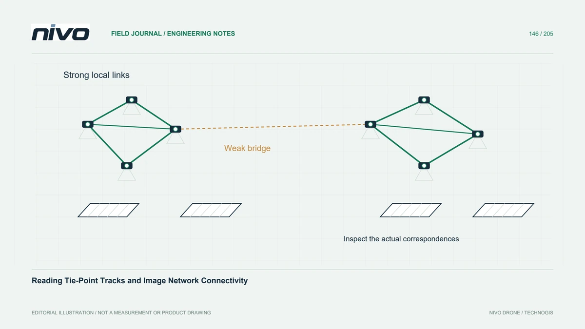
A tie-point track links observations believed to represent the same scene feature across images. Its length describes how many image observations support that feature, but length alone does not establish correctness or useful geometry. A track concentrated in almost identical viewpoints differs from one connecting diverse views. Read the track evidence together with camera positions, image quality, and the physical surface being reconstructed.
Read the network as well as the total
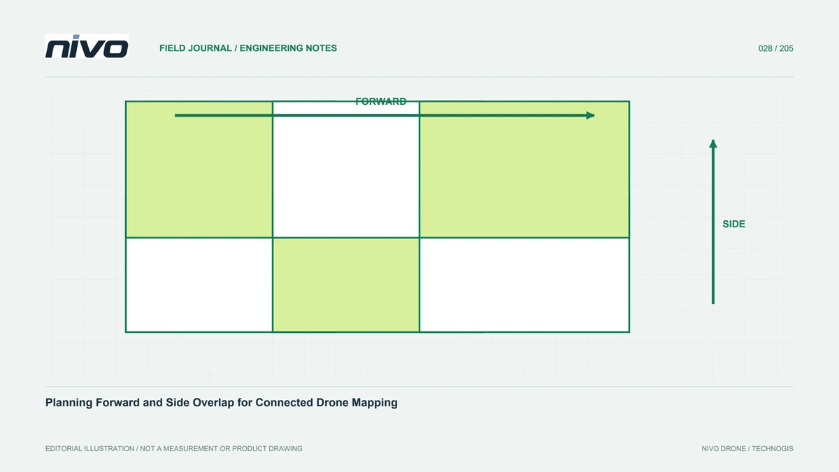
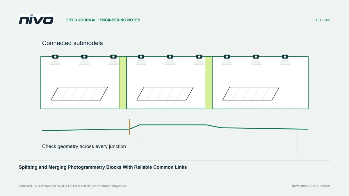
An overall feature count can hide weak connections between blocks. Inspect the image match graph for isolated photographs, separate components, and narrow bridges supported by only a few connections. Check whether strips connect across the project rather than only along their own direction. A large registered-image percentage can still leave a critical junction or edge insufficiently linked to the main reconstruction.
Inspect spatial distribution within images
Useful observations should be distributed across image areas and across the site. Features clustered on one textured corner leave other image regions weakly constrained. Review feature or track heatmaps and relate them to shadows, uniform surfaces, and image-edge behaviour. Long tracks on one building do not compensate automatically for missing connections over an adjacent open field where the deliverable also needs reliable geometry.
Question repeated or moving textures
Repeated roof panels, crop rows, and similar objects can produce plausible-looking but incorrect correspondences. Moving vehicles or vegetation can also violate the assumption of a stable scene. Inspect representative matches near suspicious connections and compare the reconstructed camera arrangement with acquisition records. A graph line indicates an accepted computational relationship; it is not independent proof that the underlying correspondence is physically correct.
Repair the actual connection problem
In a hypothetical warehouse mapping block, investigate an isolated strip beside repetitive roofs. First check image sharpness, capture sequence, and whether suitable overlap exists in stable textured areas. Then test justified matching settings or carefully reviewed masks on a small subset. If observations are genuinely absent, identify supplementary acquisition rather than increasing feature numbers until a visually connected graph appears.
Keep evidence before dense processing
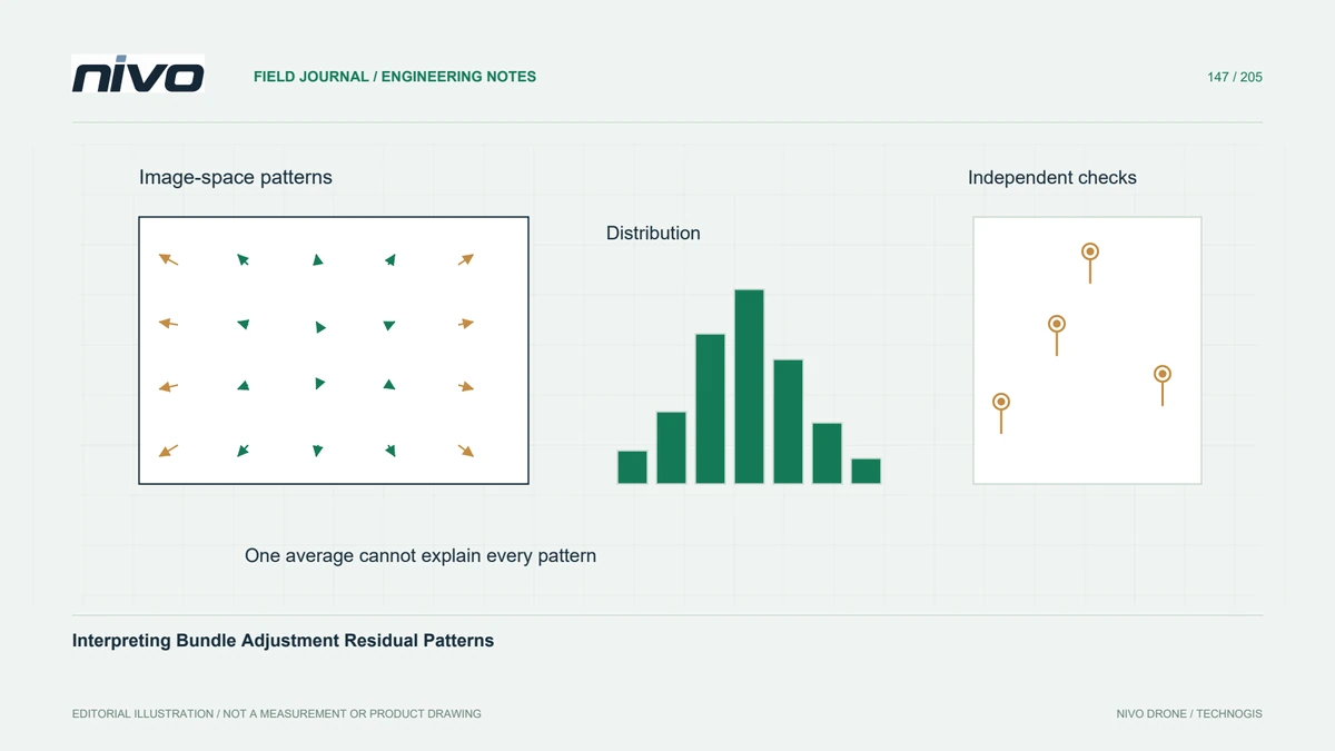
Save the network view, registration summary, track distribution, and decisions about rejected or isolated images before dense processing. Record which changes improved the actual weak region and verify the resulting geometry with independent checks. Acceptance should establish sufficient, plausible connections for the intended coverage. Dense matching can add surface observations later, but it cannot substitute for a defensible camera network and correctly linked image evidence.